If this is your first visit, be sure to
check out the FAQ by clicking the
link above. You may have to register
before you can post: click the register link above to proceed. To start viewing messages,
select the forum that you want to visit from the selection below.
---------- Post added at 22:39 ---------- Previous post was at 22:25 ----------
Looking back on Toyota F1 engine development
How did we travel from the high-boost era of the 1980s to today’s high-revving naturally aspirated Formula One engines? The journey was in two phases. The first spanned the 1990s, when engine manufacturers first started aggressively exploring the region above 12,000 rpm, steadily moving towards 18,000 rpm (which today by regulation is the engine speed limit). The second phase, over the past ten years, only briefly witnessed further speed increases, to 20,000 rpm, and was characterised by an increasing mileage requirement. Instead of having to run only one Grand Prix race, these hugely stressed engines now have to run three complete meetings. In tracing the development of the Toyota Formula One engine, we explore here in depth that second phase. In its final 2.4 litre V8 frozen-specification guise, the engine developed by TMG continues to be used to power the test car that Toyota fields for new tyre supplier Pirelli; TMG is Toyota’s motorsport facility based in Cologne, Germany, which ran the Japanese company’s Formula One programme.
The design of the V8 TMG produced for Toyota was the subject of a Dossier in RET issue 49 (1) and here, thanks to further generous cooperation from TMG, which both designed and developed it, we are able to chart its evolution from Toyota’s initial decision to enter Formula One. With all Formula One engines by regulation now frozen in specification, this is the revealing and exclusive story of how a state-ofthe- art contemporary Grand Prix power unit came about.
Introduction
The Formula One turbo era of the 1980s lasted until 1988, after which all engines had to be naturally aspirated. Initially the displacement limit was 3.5 litres, and in the early ’90s the FIA also decreed 3.5 litre naturally aspirated engines for Group C. At the time, Toyota was active in Prototype racing and it designed a naturally aspirated 3.5 litre V10 for its 1992 Group C car.
Group C racing fizzled out in 1994 and Toyota did not follow archrival Peugeot in developing a spin-off Formula One engine. Then, for 1995, the Formula One displacement limit was cut to 3.0 litres. By this stage the FIA had clamped down on fuel development, enforcing gasoline that was little better than regular roadside unleaded in terms of performance enhancement. The 1995 3.0 litre Formula One engines were a mixture of V8, V10 and V12 configurations.
As engine speed steadily rose, undoubtedly the strongest 3.0 litre engine was the Renault V10, which in 1995 produced about 700 bhp at 15,600 rpm. By 1997 the best engines had gone on to eclipse 750 bhp, for example the Ilmor V10 making 760 bhp at 16,200 according to designer Mario Illien. The rival Renault and Ferrari V10s made a comparable output.
By 1998 all Formula One engines were V10s, and that year new chassis and tyre regulations left the cars inadequately shod at the rear. That put the emphasis on preservation of the rear tyres and, from the engine perspective, weight was more significant than ever as designers strove to push the car’s centre of gravity forwards. A front-end timing drive was called for and there was a trend to linerless aluminium alloy cylinder blocks, to save weight.
The years 1998 to 2000 were also notable for the exploitation of aluminium-beryllium pistons by Ilmor Mercedes, these both saving weight and increasing thermal resistance over the regular 2618 aluminium alloy. New materials regulations for 2001 effectively outlawed that beneficial approach, decreeing 40 GPa/(g/cc) as the maximum specific strength for all components (for 2000 that figure had been decreed as the maximum for all except internal engine components).
In the meantime, having reached 800 bhp in 1999, by 2000 the Ilmor engine was running to a maximum speed of 18,000 rpm, and was then making peak power of 820 bhp at 17,500 rpm. That was the state of the art in a season for which the FIA decreed there to be a maximum of ten cylinders. That move scuppered the plans of Toyota and Cosworth, both of which had V12 projects underway.
2000-2001
When, in January 2000, Toyota switched instead to a V10 3.0 litre engine, the design team was led by Luca Marmorini, previously a Ferrari Formula One engine engineer (he remained with TMG until 2009). Soon after embarking on the design of a V10 he remarked to the author that since the Toyota race programme was not scheduled to start until 2002, the new engine could not afford to be a conservative design, otherwise progress by its rivals would surely leave it wanting.
Toyota’s initial Formula One engine was officially designed RVX-01 (Racing Vee Ten – 01). It was known in-house as the ‘B’ engine, following on from the V12 design. It had a 90º rather than the conventional 72º measure as its bank angle (this being an approach pioneered by the 2000 Ferrari V10). Linerless, it had a 95.1 mm bore, a front-end timing drive and, at the outset, its weight was 109.55 kg.
The B engine had its first dyno run in September 2000, its first track test in May 2001. In the summer of 2001 the strongest Formula One engine was almost certainly the BMW V10, which was developed to produce 880 bhp according to recently published information from the company (2). By August 2001, Toyota had engine speed 500 rpm up on initial testing and then, at close to 18,000 rpm; its as-yet unraced V10 made almost 800 bhp.
2002
The lessons of the B engine led to a redesigned C, which followed the same basic pattern and came in essentially at the same weight (109.11 kg). With this engine Toyota made its Formula One debut at the start of the 2002 season. Toyota has never published power output figures for its Formula One engines. Each year at the midseason British Grand Prix event, RET estimates the power of all current Formula One engines, not by any quasi-scientific form of measurement but by the straightforward approach of asking key engine and chassis engineers – who know their own output and go to great lengths to judge the performance of their rival units against it – to establish a consensus table. Toyota was estimated by this method to have reached 830 bhp mid-season with its first Formula One race engine. In 2002, BMW produced the first V10 to reach 19,000 rpm, and by the end of that season its output was 895 bhp.
2003
In an effort to take Toyota to the sharp end of the grid, for 2003 there was a complete redesign of the previous B/C engine. Reflecting increasing engine speed, the new D engine increased the bore from 95.1 mm to 96.8 mm, yet was nevertheless more compact. The D also had a lower crankshaft height than its predecessors, helping to lower the centre-of-gravity height. At 101 kg, it was significantly lighter than the C engine. It also offered a step up in performance.
The FIA brought in overnight parc ferme regulations for 2003 Formula One events, so a car had to race with the engine used in qualifying. While this added only a marginal amount to the required mileage, it did add the toughest period of running for any engine. Nevertheless, by mid-2003, both BMW and Honda had exceeded 900 bhp. At the British Grand Prix, RET estimated 910 bhp for those engines and 890 bhp for the D-spec, which was the first Toyota V10 to run to 19,000 rpm. It was developed to produce more than 900 bhp by the end of the 2003 campaign. BMW claims it reached 940 bhp by the end of 2003 (2).
2004
For 2004 there was a significant increase in required mileage, the engine now mandated by the FIA to run the entire race weekend. Mileage thus went from about 370-400 km (qualifying and race) to 550-700 km (the exact figure according to team usage policy, and typically about 600-650 km). In view of this, the E engine was essentially an evolution of the D engine with painstaking detail work providing the required increase in mileage. Despite that, the best part of a kilo was shaved from the weight; the E weighed about 100 kg.
Google Traducción
¿Cómo hemos de viaje de la época de alto impulso de la década de 1980 a altas revoluciones de aspiración natural hoy en día los motores de la Fórmula Uno? El viaje fue en dos fases. La primera abarcó la década de 1990, cuando los fabricantes de motores comenzó agresivamente a explorar la región por encima de 12.000 rpm, constantemente en movimiento hacia el 18.000 rpm (que en la actualidad por la regulación es el límite de velocidad del motor). La segunda fase, en los últimos diez años, sólo brevemente se registraron aumentos aún más la velocidad, a 20.000 rpm, y se caracterizó por una exigencia de aumentar el kilometraje. En lugar de tener que ejecutar un solo Gran Premio, estos motores de enorme hincapié ahora tiene que correr tres encuentros completos. Al trazar el desarrollo de la Fórmula Uno Toyota motor, exploraremos aquí en profundidad que la segunda fase. En sus últimos 2,4 litros V8 congelados especificaciones apariencia, el motor desarrollado por TMG sigue siendo utilizada para alimentar el coche de pruebas de que Toyota campos para nuevas proveedor de neumáticos Pirelli, TMG es la instalación de Toyota Motorsport, con sede en Colonia, Alemania, que se desarrolló la compañía japonesa de Fórmula Uno de estos programas.
El diseño de la TMG V8 producido por Toyota fue objeto de un expediente en la edición de RET 49 (1) y aquí, gracias a la generosa cooperación más lejos de TMG, que tanto ha diseñado y desarrollado, somos capaces de trazar su evolución desde el inicial de Toyota decisión de entrar en la Fórmula Uno. Con todos los motores de la Fórmula Uno por la regulación ahora congelado en el pliego de condiciones, esta es la historia que revela cómo y exclusiva de un estado-del-arte contemporáneo Gran Premio de unidad de potencia se produjo.
Introducción
La Fórmula Uno era del turbo de la década de 1980 duró hasta 1988, después de que todos los motores tuvieron que ser de aspiración natural. Inicialmente, el límite de desplazamiento fue de 3,5 litros, y en los años 90 la FIA también decretó 3,5 litros motores de aspiración natural para el Grupo C. En ese momento, Toyota era activo en las carreras de prototipos y se diseñó una aspiración natural de 3.5 litros V10 de 1992 su grupo C coche.
Grupo C carreras fracasó en 1994 y Toyota no siguió su archirrival Peugeot en el desarrollo de un spin-off de Fórmula Uno del motor. Entonces, para el año 1995, la Fórmula Uno, limitar el desplazamiento se redujo a 3,0 litros. En esta etapa de la FIA ha tomado medidas drásticas en el desarrollo de combustibles, la aplicación de la gasolina, que era mucho mejor que la carretera regular sin plomo en términos de mejora del rendimiento. Los motores de 3,0 litros 1995 de la Fórmula Uno eran una mezcla de V8, V10 y V12 configuraciones.
Como la velocidad del motor aumentó en forma sostenida, sin duda, el más fuerte motor de 3,0 litros V10 fue el Renault, que en 1995 produjo cerca de 700 CV a 15.600 rpm. En 1997 los mejores motores se había ido a Eclipse 750 CV, por ejemplo, el V10 Ilmor hacer 760 CV a 16.200 de acuerdo con el diseñador Mario Illien. El rival de Renault y Ferrari V10 hizo una salida comparable.
Antes de 1998 todos los motores de la Fórmula Uno se V10, y que el chasis nuevo año y los reglamentos de los neumáticos de los coches a la izquierda inadecuadamente calzados en la parte trasera. Que ponen el énfasis en la preservación de los neumáticos traseros y, desde el punto de vista del motor, el peso era más importante que nunca, ya que los diseñadores se esforzaron para empujar el centro del coche de gravedad hacia delante. Una unidad de tiempo front-end se pidió y se observó una tendencia a bloques sin revestimiento de aleación de aluminio del cilindro, para ahorrar peso.
Los años 1998 a 2000 se destaca también por la explotación de los pistones de aluminio y berilio-por Ilmor Mercedes, estas dos resistencias de ahorro de peso y aumentar la térmica sobre la aleación de aluminio regular de 2618. Regulaciones sobre materiales nuevos para el año 2001 efectivamente fuera de la ley que el enfoque de beneficio, decretando 40 GPa / (g / cc) como la fuerza máxima específica para todos los componentes (para el año 2000 esa cifra había sido decretado como el máximo para todos, excepto los componentes internos del motor).
Mientras tanto, después de haber llegado a 800 CV en 1999, en el año 2000 el motor Ilmor fue corriendo a una velocidad máxima de 18.000 rpm, y entonces hacer una potencia máxima de 820 CV a 17.500 rpm. Ese era el estado del arte en una temporada para la que la FIA decretó que haya un máximo de diez cilindros. Que se mueven echó por tierra los planes de Toyota y Cosworth, los cuales habían V12 proyectos en curso.
2000-2001
Cuando, en enero de 2000, Toyota cambió su lugar con un motor V10 de 3.0 litros, el equipo de diseño dirigido por Luca Marmorini, anteriormente un Ferrari de Fórmula Uno ingeniero de motor (se quedó con TMG hasta 2009). Poco después de emprender el diseño de un V10 comentó al autor que, dado que el programa de carreras de Toyota no estaba programado para comenzar hasta el año 2002, el nuevo motor no podía permitirse el lujo de ser un diseño conservador, de lo contrario el progreso de sus rivales sin duda deja querer .
Inicial de Toyota de Fórmula Uno del motor fue diseñado oficialmente RVX-01 (Racing Vee Diez - 01). Era conocido en casa como motor de la "B", a raíz del diseño V12. Tenía un 90 º lugar de los convencionales 72 º como medida de su ángulo de inclinación lateral (que es un planteamiento iniciado por el V10 2000 Ferrari). Sin revestimiento, que tenía un 95,1 mm de diámetro, una unidad de tiempo front-end y, desde el principio, su peso era de 109,55 kg.
El motor B tuvo su primer jonrón banco de pruebas en septiembre de 2000, su pista de pruebas por primera vez en mayo de 2001. En el verano de 2001 el mayor motor de la Fórmula Uno era casi seguro que el V10 de BMW, que fue desarrollado para producir 880 CV de acuerdo a la información recientemente publicada de la compañía (2). En agosto de 2001, Toyota tuvo la velocidad del motor a 500 rpm en la prueba inicial y luego, a cerca de 18.000 rpm, y su aún sin unraced V10 hace casi 800 CV.
2002
Las lecciones del motor B condujo a un nuevo diseño de C, que siguió el mismo patrón básico y vino en esencia, en el mismo peso (109,11 kg). Con este motor, Toyota hizo su debut en la Fórmula Uno en el inicio de la temporada 2002. Toyota no ha publicado las cifras de potencia de salida de la Fórmula Uno los motores. Cada año en la mitad de la temporada de eventos GP de Gran Bretaña, RET estima que el poder de todos los actuales motores de la Fórmula Uno, no por cualquier otra forma cuasi-científico de la medida, sino por el método directo de pedir a los principales motores y los ingenieros de chasis - que conocen su propia producción y van todo lo posible para juzgar el desempeño de sus unidades rival contra el que - para establecer una mesa de consenso. Toyota fue estimada por este método que ha alcanzado 830 CV a mitad de temporada con su motor de carrera de Fórmula Uno. En 2002, BMW produjo el primer V10 para llegar a 19.000 rpm, y al final de esa temporada su producción fue de 895 CV.
2003
En un esfuerzo por llevar a Toyota a la punta de la red, para el año 2003 hubo un rediseño completo de la anterior B / C del motor. Como reflejo de aumentar la velocidad del motor, el nuevo motor D aumentó el diámetro de 95,1 mm a 96,8 mm, sin embargo, era sin embargo más compacto. La D tuvo un auge del cigüeñal inferior a sus predecesores, ayudando a reducir la altura del centro de gravedad. En 101 kg, fue mucho más ligero que el motor C. También ofreció un paso adelante en su rendimiento.
La FIA llevó en la noche parc ferme regulaciones para el 2003 de Fórmula Uno los eventos, así que un coche tuvo que correr con el motor utilizado en la clasificación. Si bien esto añade una cantidad marginal a las millas necesarias, se ha agregado el periodo más duro de funcionamiento de cualquier motor. Sin embargo, a mediados de 2003, los dos BMW y Honda se había excedido 900 CV. En el Gran Premio de Gran Bretaña, estima RET 910 CV para los motores y 890 CV para el D-spec, que fue el primer motor V10 de Toyota para ejecutar a 19.000 rpm. Fue desarrollado para producir más de 900 CV para el final de la campaña de 2003. BMW afirma que llegó a 940 CV a finales de 2003 (2).
2004
Para el año 2004 hubo un aumento significativo en el kilometraje requerido, el motor ahora el mandato de la FIA para correr el fin de semana entero. Kilometraje por lo tanto fue de unos 370-400 km (calificación y la carrera) a 550-700 km (la cifra exacta de acuerdo a la política del equipo de uso, y por lo general alrededor de 600-650 km). En vista de esto, el motor E era esencialmente una evolución del motor D con el trabajo meticuloso detalle proporcionando el necesario aumento de kilometraje. A pesar de ello, la mejor parte de un kilo se afeitó por el peso, la E pesaba unos 100 kg.
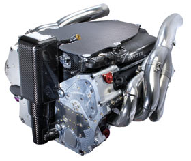
Toyota's RVX09 engine
the Toyota RVX-09 V8 is an ideal engine, having a well-tailored bore size (no alteration of has been possible since the first stage of the current freeze was implemented for 2007). The 2009 RVX-09 V8 is derived from TMG’s 2005 3.0 litre V10 engine, which had a 96.8 mm bore and ran to 19,200 rpm.
The baseline: E41/4
The BMW-Williams Formula One alliance began with testing in 1999 using a contemporary Williams chassis converted from its usual Supertec engine. The new BMW E41 was of similar configuration, size and weight to that 72º V10, which was a derivative of the Renault engine designed in 1997. In fact, design of the E41 had also begun in 1997, when the BMW board gave the green light to a return to Formula One, and it was the third iteration that started racing in 2000. By 2000, the top rival engines were smaller and lighter with a lower centre of gravity, to the benefit of the overall car package. “We won’t have the most powerful or the lightest engine this year,” remarked Dr Theissen at the January 2000 launch of the Williams-BMW. “This season we will not have engine power at the level of Ferrari and McLaren-Mercedes, or the same engine weight. They can take risks in establishing a new benchmark. Our aim for this year is to have an engine which is stable, in order to establish ourselves in Formula One.”
Although F1 racing engines have lost some of the attractiveness they used to have when the regulations allowed more freedom, every single design currently in use is still a highly advanced piece of engineering that has required lots of time and thought. An engine is the only power source of a Formula One car - apart from the KERS systems in 2009 which are indirectly charged by the power generated by the engine - and is a structural part of the chassis.
Facts and figures
Because of the regulations and engineering optimisations, all curent engines are of a similar type, and feature the following similarities:
•All F1 engines are naturally aspirated V8's of 2400cc
•Engines are limited to 18,000rpm
•The weight is exactly 95kg (each manufacturer easily reaches this regulated minimum weight)
•Engine blocks are constructed of forged aluminium alloy, because of the weight advantages it gives in comparison to steel. Other materials would maybe give some extra advantages, but to limit costs, the FIA has forbidden all non-ferro materials.
•Crankshaft and piston rods are Iron based for strength.
•At its maximum pace the current V8 engines consume around 60 litres of petrol for 100km of racing.
•It's not exactly known how much oil such a top engine contains, but this oil is for 70% in the engine, while the other 30% is in a dry-sump lubrication system that changes oil within the engine three to four times a minute.
•Before its first track time and after each race, each engine is tested on an engine dyno to validate its performance and identify problems. A videoclip of Renault's RS24 on the dyno can be found here.
Evolution of engine design
All current engines run by the competing F1 teams are very similar due to the very stringent regulations that have increasingly come into play since 2006. Until that time, all car manufacturers involved in F1 were effectively outracing each other in a spending race. It is not a lie to claim that in the years after 1995, the manufacturer who invested most and could hire most people could produce the best engine.
Back in 1997, Ford Cosworth started a furious battle for weight reduction as their CR1 at the time was at least 25kg lighter than any other. Although they suffered some reliability problems troughout the season, the engine was an example for the others, as it allowed the team to shift ballast in the car to benefit the car's handling.
As a reaction to this weight shedding, the the 1998 Mercedes-benz engine was possibly one of the most revolutionary engines ever built, making performance gains and drastic weight cuts at the same time. It quickly proved good enough to be the basis of Mika Hakkinen's two consecutive world titles with McLaren Mercedes. When in 2000, the FIA decided to limit the use of Berillium alloys - to a maximum of 5 mass percentage - due to being poisonous in high quantities, Mercedes struggled for years to recover from that setback - they could not match anymore the power of the at that time mighty Ferrari and BMW engines.
By the end of 2005, most of the teams had converged their designs to 3 litre V10's with an internal angle of 90°. The teams' designers had come to the conclusion that 90° was the best compromise between performance and stiffness of the engine itself.
That same year, some 3l V10 engines were producing more than 980hp and running very close to the 1000hp mark, a figure that was never reached since the ban on turbo engines. It was a sign for F1's governing body to change the regulations as top speeds at Monza of 370km/h were deemed hazardous for the drivers as well as the spectators. The maximum capacity was thus reduced to 2.4l and the cylinder count to 8. Additionally, the FIA ruled that an engine freeze would come into effect a year later to put an end to the spending race.
Only 2 years later however, halfway through 2008, the FIA and several teams who strictly followed the rules - including the likes of Toyota and Renault - found that the regulations still allowed too much freedom. It appeared that over the last year, Mercedes and Ferrari had been able to add up to 40hp to their engines as so called "reliability updates", while others had followed the engine freeze more strictly. Several meetings with FIA officials and the teams' principals then resulted in an equalisation of the engines, in which the less powerful could put on several updates to be on par in the next years.
Even so, without fiercely looking for improvements, a current F1 engine is a highly interesting piece of engineering, in total consisting of 5000 seperate parts, 1500 of which are moving. It is estimated that when in operation, a new F1 engine can produce around 720hp, but would be able to reach up to 780hp and above 20,000rpm if there would not be a limit on engine revolutions.
Difference with road engines
•Higher volumetric efficiency. VE is used to describe the amount of fuel/air in the cylinder in relation to regular atmospheric air. If the cylinder is filled with fuel/air at atmospheric pressure, then the engine is said to have 100% volumetric efficiency. Turbo chargers for instance can increase VE to above 100% while normally aspirated engines tipically run anywhere between 80% and 100%. In this region however, a Formula One engine usually can achieve a higher VE than normal road engines because of their highly optimised intake manifolds.
•Unfortunately, from the total fuel energy that is put into the cylinders, averagely less than 1/3 ends up as useable horsepower. Ignition timing, thermal coatings, plug location and chamber design all affect the thermal efficiency (TE). Low compression street engines may have a TE of approximately 0.26, a racing engine may reach approximately 0.34. This seemingly small difference results in a difference of about 30% (0.34 - 0.26 / 0.26) more horsepower than before.
•From all that power generated, part of it is used by the engine to run itself. The left over power is what you would measure on a dynamometer. The difference between what you would measure on the dyno and the workable power in the cylinder is the mechanical efficiency (ME). Mechanical efficiency is affected by rocker friction, bearing friction, piston skirt area, and other moving parts, but it is also dependent on the engine's RPM. The greater the RPM, the more power it takes to turn the engine. This means limiting internal engine friction can generate a large surplus in power output, and where in F1 the stress is on power, on the road it is also on fuel consumption.
These main optimization necessities are what makes Formula One engine design difficult. At the end of the line, an F1 engine revs much higher than road units, hence limiting the lifetime of such a power source. It is especially the mechanical efficiency that causes Formula One engines to be made of different materials. These are necessary to decrease internal friction and the overall weight of the engine, but more importantly, limit the weight of internal parts, e.g. of the valves, which should be as light as possible to allow incredibly fast movement of more than 300 movements up and down a second (this at 18.000 rpm).
Another deciding point trying to reach a maximum of power out of an engine is the exhaust. The minor change of lenght or form of an exhaust can influence the horsepowers drastically. Although variable outlet systems are not allowed, the exhaust system on a race car does not feature a muffler, lacks a katalysator and is specially made to whitstand temperatures as high as 1200°C, a lot more than what is achieved with a regular road engine.
Engine design phylosophies
Considering internal combustion engines (thus leaving out oscillating and Wankel rotary combustion engines), there are basically three different ways of building an engine. The difference here is how the cylinders are placed compared to each other.
•Inline engines, where all cylinders are placed next to (or after) each other are not used in Formula One since the 60's. While the engines are small, they are long and therefore require a heavy cranckshaft.
•Boxer engines are actually one of the best ways to build an engine, if all external factors allow it. Two cylinder rows are placed opposed to each other. You could consider a boxer engine as being a 180° V-angle engine design. These engines became popular in F1 because of the low centre of gravity and the average production costs, but later on disappeared out of the picture as this type of engine is not sufficiently stiff enough to whitstand the car's G-forces in cornering conditions. Ferrari for instance have run 12 cylinder boxer engines from 1970 to 1980 before moving to a 120° V-angle engine.
•V-type engines, as currently used in all F1 cars. The V is in fact the geometrical angle that seperated the two cylinder banks from each other where the crankshaft can be considered the origin of the angle. Obviously for this type of engine the size of the V is a major factor and must be decided in the first phases of the engine design. Previously, engines have been designed with angles such as 60° V12 or 72° V10. Although it has historically been an interesting evolution to see the differences between the teams' engines, the FIA have fixed the engine type to 90° V8 models.
Since the introduction of the Ford Cosworth DFV, an engine in a F1 car is a stressed member of the chassis, meaning that it is an integral part of the car. Before that idea, a chassis was built as a tube frame with the engine placed in it afterwards, while now a chassis would fall apart if no engine was fitted. A current engine is bolted in between the rear end of the monocoque and the frontal side of the gearbox. As of that time, V-type engines have gradually pushed out any other engine type because they are compact and can be constructed very rigidly without requiring further strengthening to the chassis to ensure stiffness.
Contrary to boxer or flat engines, V-angled combustion engines pose an extra design problem, as it is crucial for an engine's performance that the V-angle is chosen wisely. This angle important to ensure a correct firing sequence and hence also influences its primary balance.
Calculating possible V angles for a specific number of cylinders is fortunately not a daunting task. If you consider that every combustion cycle takes 2 turns - intake and combustion phase - of the crankshaft, and a full circle is 360°, the engine's included V-angle x the number of cylinders must be a function of 720 in order to achieve evenly spaced cylinder firing and primary balance.
That is also why a boxer engine is an ideal layout. The cylinders are opposed at 180° so having 2 or 4 or 6 or 8 or 10 or 12 isn't that big. Perfect primary balance is easy to achieve, as long as the reciprocating and rotating parts are in balance and, the firing order is always evenly spaced. A few examples make it clear why several specific angles have been very popular in F1 engine design:
•As mentioned earlier, Ferrari have used a 60° V12 or 120° V12 engine. As for the first option, divide 720° by 12 cylinders and you get 60. You get 120° when you imagine a V12 as two aligned V6 engines.
•Renault's extremely successful 72° V10 engines share the same thoughts. It is the perfect bank angle for any V10 engine if a boxer is not an option. One cylinder is fired every time the cranckshaft has completed 72° so that after 2 turns every single piston has gone through one complete cycle.
•Currently every team runs 90° V8 engines but not only because the regulations prescribe so. Also this is a perfect angle and meets the size requirements set by the aerodynamicists.
•Contrary to these optimal choices, there have also been unusual uses. For instance the 2005 90° V10 engines that everyone but Renault were using. While they may have been more interesting for other reasons, it's performance could theoretically not beat Renault's RS25 that was a 72° V10. The 90° V10 engines hence had either offset crankpins or a funny firing order.
•Before their RS24 Renault was trying a revolutionary design as they designed a 112° V10. Although the engine evolved from RS21 to RS23 and was beneficial in terms of the centre of gravity it was finally abandoned. The engine could not reach competitively high rpms since the uneven firing order introduced unwanted vibrations in the engine.
Cranckshaft design
Although the V8 with the now compulsory cylinder angle of 90 degrees may look like a sawn-off V10, technically it is an entirely separate concept with its own specific requirements. The V8 has a distinct firing sequence and demands a fundamentally different crankshaft design. Whereas a 72-degree offset crankshaft was used in most V10 Formula One engines, V8 powerplants can feature crankshafts with either four throws spaced at 90 degrees or four throws spaced at 180 degrees. Standard production engines are fitted with 90-degree crankshaft variants due to their better dynamic attributes, but a 180-degree crankshaft is favoured in racing car engine design. The improved performance this allows offsets the disadvantages in terms of dynamics.
Cooling
With such a low thermal efficiency, cooling of any internal combustion engine is vital for its correct operation. Basically, an F1 cooling system is the same as in any regular road car, as engine cooland and oil is pumped through a radiator to cool down before completing another cycle through the engine.
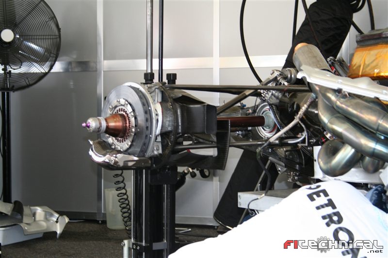
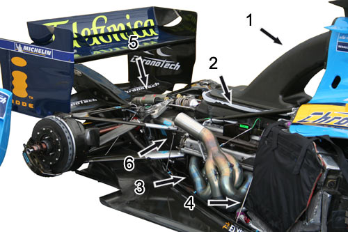
However, due to the space restrictions and aerodynamic requirements of a race car, the positioning of these components is completely different. The following shows the internals of a championship winning Renault R25 of 2005, included with its Renault RS25 engine (2). The flat panels located nearly vertically in the front of the side pods are the radiators (4). While in this picture the radiator is covered with a protective hose, it is not during running as air passes through the aluminium fins of the radiator. Their position however varies considerably in different cars as they are influenced by the aerodynamic and weight distribution requirements of a car.
Contrary to popular belief, the air inlet above the driver's head is not part of the cooling system but instead provided the engine's cylinders with air to be mixed with fuel for combustion. It is commonly thought that the purpose of this is to 'ram' air into the engine like a supercharger, but the airbox does the opposite. The carbon fibre duct (1) gradually widens out as it approaches the engine, effectively creating a venturi and a suction effect on the small air inlet. The shape of this ducts and inlet however must be carefullly designed to both fill all cylinders equally and not harm the exterior aerodynaimcs of the engine cover, all to optimize the volumetric efficiency.
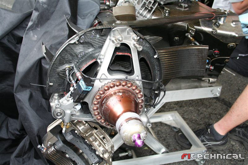
Marked with (3) is the engine exhaust system while (5) and (6) identify the rear suspension that is fitted onto the gearbox.
Transmission
The transmission of any car is considered to be all intermediate gears and systems to get the engine rotational power to the wheels. In reality this comes down to the gearbox and differential, which are both assembled into the gearbox casing. Just as with the engine, this casing - often made of titanium or carbon fibre - is also a structural part of the chassis and is firmly bolted onto the rear end of the engine. More can be found in the specific article about F1 transmissions.
Regulations
The current regulations on Formula One engines can be summarised as follows. These specifications have become more strict during recent years in an attempt to limit costs and decrease performance. You can find an evolution of the most important regulations per era in the safety section. As this is only an exerpt of the most important regulations on engines, you would need to see the official FIA technical regulations before you start to design a Formula One engine yourself.
Specification
Only 4-stroke engines with reciprocating pistons are permitted.
Engine capacity must not exceed 2400 cc.
Crankshaft rotational speed must not exceed 18,000rpm.
Supercharging is forbidden.
All engines must have 8 cylinders arranged in a 90º “V” configuration and the normal section of each cylinder must be circular.
Engines must have two inlet and two exhaust valves per cylinder.
Only reciprocating poppet valves are permitted.
The sealing interface between the moving valve component and the stationary engine component must be circular.
Dimensions, weight and centre of gravity
Cylinder bore diameter may not exceed 98mm.
Cylinder spacing must be fixed at 106.5mm (+/- 0.2mm).
The crankshaft centreline must not be less than 58mm above the reference plane.
The overall weight of the engine must be a minimum of 95kg.
The centre of gravity of the engine may not lie less than 165mm above the reference plane.
The longitudinal and lateral position of the centre of gravity of the engine must fall within a region that is the geometric centre of the engine, +/- 50mm. The geometric centre of the engine in a lateral sense will be considered to lie on the centre of the crankshaft and at the mid point between the centres of the forward and rear most cylinder bores longitudinally.
Variable geometry systems are not permitted
Materials
Magnesium based alloys, Metal Matrix Composites (MMC’s) and Intermetallic materials may not be used anywhere in an engine
Coatings are free provided the total coating thickness does not exceed 25% of the section thickness of the underlying base material in all axes. In all cases the relevant coating must not exceed 0.8mm.
Pistons must be manufactured from an aluminium alloy which is either Al-Si ; Al-Cu ; Al-Mg or Al-Zn based.
Piston pins, crankshafts and camshafts must be manufactured from an iron based alloy and must be machined from a single piece of material.
A supplementary device temporarily connected to the car may be used to start the engine both on the grid and in the pits.
Electronics
Every one of the 22 Formula One cars on the grid is dependent upon sophisticated electronics to govern its many complex operational systems. Each Formula 1 car has over a kilometre of cable, linked to about 100 sensors and actuators which monitor and control many parts of the car. Rarely a race goes by without a car retiring with electrical problems, indicating the important role that this technology has in modern F1 cars.
Engine Management
The 800 bhp of a modern F1 engine is largely a result of a complex electronic control unit (ECU) that controls the many systems inside an engine so that they work to their maximum at every point around the lap. Engine mappings can change completely from circuit to circuit depending upon the nature of the track. At Monaco for instance, the engine control system will help the driver have more control on the throttle input by making the first half of the pedal movement very sensitive, and the latter half less sensitive. This means that the driver can have great control on the throttle for the twisty corners, so that it is easier to limit the acceleration out of corners so not to spin the wheels. At somewhere like Hockenheim, the driver has to jump on the throttle more out of the chicanes, rather than gradually applying full throttle. The accelerator will be set so that only a small movement will result in full engine acceleration. It is also possible to iron out any unplanned movements of the throttle such as when a driver travels over a bump and his foot may move slightly.
The engine control system can cut out the jumps of the throttle and keep full throttle down the straight, even on bumpy tracks. This is all possible because there is no direct link between the engine and the accelerator. The accelerator position is sensed using an actuator, and this signal is then sent to the engine control system, from where it is passed onto the engine. An engine ECU is much more than a device for making the throttle more or less sensitive. The ECU controls the inlet trumpet height, fuel injection among other things to try to get the maximum torque out of the engine. In the modern world of electronics, the ECU monitors many of the engine parameters including RPM, to control the torque output from the engine. This means that the modern day F1 accelerator acts more like a torque switch than a simple fuel input controller. F1 engines are so complex that they are designed to run in a small power band between 15000 - 18000 rpm, and the electronic monitoring and controlling of the engine parameters are crucial in keeping the engine in this working region. This working region is where torque is virtually constant, and letting the engine get below the lower limit would see a sudden drop off of torque, until the engine began to rev in the working region, where the torque would come in suddenly again, probably promoting wheelspin.
Other ECU functions
The ECU also controls the clutch, electronic differential and and the gearbox. The clutch is controlled by the driver to start the car from rest, but not during gear changes. Although the driver modulates the throttle like on a road car (although with his hand) there is no direct link to the clutch - it is all electronic. The ECU engages and disengages the clutch as the driver moves the paddle behind the steering wheel. The ECU will also depress the clutch if the car spins to stop it stalling. The FIA introduced the anti-stall device in 2000 to prevent cars stalling after a spin and being left dangerously i the middle of the track. The ECU is also responsible for changing gears in under 100 milliseconds. The electronics allow the driver to keep his foot flat on the throttle during up-shifts, and blip the throttle on down-shifts to match engine speed with transmission speed to prevent driveline snatch. The final area controlled by the ECU is the differential. Modern F1 cars have electronic differentials which monitor and control the amount of slip between the rear wheels on entry and exit of corners. This is often adjusted for different driving styles to try to keep the rear end of the car in control during all phases of a corner.
Data acquisition - Telemetry
Every aspect of the car, whether it be speed, brake and engine temperature, suspension movements, ride height, pedal movements and g-force are measured and controlled from the pit whilst the car is out on the track. Teams usually take over 30 kg of computer equipment to each Grand Prix just to help the drivers and engineers to find the right set-up and cure any car problems. An F1 car has two types of telemetry: The first is a microwave burst that is sent to the engineers every time the car passes past the pits. This data burst can contain around 4 megabytes of information giving the engineers a vital insight into the state of the car. Another 40 or so megabytes can be downloaded from the car when it returns to the pits, so no part of the car goes 'unwatched'. The information is downloaded by plugging in a laptop computer to the car, in a socket usually located in the sidepod or near the fuel filler. The second type is a real time system which transmits smaller amounts of information, but this time it is in 'real time'. This means the car is constantly sending out information such as its track position and simple sensor readings.
The telemetry is sent to the pits via a small aerial located on the car, usually located on the sidepod nearest to the pits. Some teams have placed the transmitter in the wing mirror that passes closest to the pits to do away with an extra aerial. When the cars returned to the pits, a small box was put over the wing mirror to prevent anyone being harmed by the radiation given out by the transmitter. This telemetry data is vital to the engineers both during the race and practice. A huge bank of computers at the back of the garage will process the information sent by the cars whilst they are on the track, and from this complex information, the team members can quickly tell whether the car is operating correctly. During a race for example, readings such as the engine temperature and hydraulic pressure are carefully examined lap by lap to ensure the car is not about to suffer any major failure. If any of one of these readings becomes varied from the normal operating state, the engineers can tell the driver to use less engine revs or drive more steadily to try to prevent a failure. Teams use software provided by their IT partners (Hewlett Packard, Compaq, TAG Electronics) that will display all of the gathered information on a screen that can be easily interpreted by the engineers. McLaren have gone a step further than most teams, developing their own system called ATLAS. Standing for Advanced Telemetry Linked Acquisition System, ATLAS displays graphs of each of the cars systems in real time at all parts of the track. Although most of the top teams have systems similar to ATLAS, it is believed that McLaren's system is one of the most advanced in F1.
McLaren preview standard ECU
The 2008 Formula 1 season will herald the start of a revolution. Research and development funds will be spent not on the duplication of common components and infrastructure, but channelled towards pure performance and road-relevant innovation. Every team on the grid will use a standardised Electronic Control Unit (ECU), and a technical partnership between McLaren Electronic Systems (MES) and Microsoft has been awarded the supply contract by the FIA. Although the unit is referred to as a ‘standard’ ECU, it’s actually a very sophisticated device, and will play a vital role in helping shape the cars of the future – on the road and track. “It’s not about dumbing down to one level, it’s about elevating everyone up,” says Peter van Manen, managing director of MES. “A common electronics platform developed from a best-of-breed system has the potential to make a big difference for the whole grid.” The ECU is the nerve centre of a Formula 1 car, controlling the power train and delivering data by dealing with more than 6000 different parameters. Reliability is a priority. The physical boxes are therefore only slightly modified versions of the units that have been supplied to other teams for a couple of years. Vital issues in any new design, such as cooling the processors, had already been addressed.
Proven hardware
“We know we’ve got something that works on a racing car,” says Jonathan Hand, technical director of MES. “We didn’t want to risk supplying a possible 12 teams with a brand new piece of electronics that had never been used on a racetrack.” Although the hardware was already proven, writing the software was a huge technical challenge. It demanded the evolution of a common code that would satisfy the needs of the teams, running a variety of different engines and gearboxes. In order not to be pulled in different directions, the team went back to basics. For example, what happens during a gearshift: “We broke down how you manage the engine behaviour during the shift, and looked at the point at which you ask the gearbox to disengage one gear and re-engage the next,” says Hand. “If you consider those steps in sequence, what you want to do with one gearbox is pretty much what you want to do with any other.”
Highly configurable
It may be a generic solution, but the ECU has detailed architecture. It’ll give teams flexibility in how they set up their software, which options they choose to enable, and how they fine-tune parameters. “The system is designed to be highly configurable, and the team that learns how to configure it best will do better,” says van Manen. Inevitably, many of the headlines revolve not around the functions the ECU offers, but one that it doesn’t: traction control. This feature, like launch control, will not be available in 2008.
The contract is testimony not only to MES’ technical prowess, but also to the level of confidentiality for which it is renowned. Some observers raised their eyebrows at the award of the ECU deal to a company that shares its name with one of the competitors. It should have come as no surprise to the teams, as they already use MES components, including the high-intensity rain lights. Formula 1’s reaction time is the envy of other industries. The rapid response is shown by the speed with which the ECU project progressed. The contract was awarded on July 5, 2006. Work began next morning. Teams were supplied with the system specification in September 2006. Production started in November and the first items were delivered on March 9, 2007. All competitors ran the unit on the racetrack in Barcelona on November 13-15. The unit’s debut at this, the first winter test, was a success: it completed 16,000km – equivalent to 50 race distances – without any real problems. “The debut performance, running during three days with no failures, was a milestone that we were all quietly very pleased about,” says van Manen. “The target was always to have something running and stable before teams started testing their new cars in 2008.” The finished version highlights the colossal leaps forward made between the initial ‘STAR system’ – which raced in 2000 – and the STAR 2 system that evolved into the 2008 ECU.
Winning combination
Its predecessor had a memory of 256 megabytes and a maximum of 192 logging channels, yet STAR 2 has a memory of up to one gigabyte and 512 logging channels. There has been a staggering progress in ECU processing power in recent years, up from about 200 million instructions per second (MIPS) to almost 2000 MIPS. The ECU on a modern high-performance sports car, such as the Mercedes-Benz SLR McLaren, uses less than 50 MIPS to run the engine and conduct all of the onboard diagnostics. The new ECU’s initial incarnation did not fully reveal the hand of the engineers behind it.
“We didn’t want to be changing everything on day one,” says van Manen. “It needs to do a job, needs to supply high-fidelity data to the teams, but also acts as a road map for what will be available as it develops.” McLaren migrated from its own internal systems to a Microsoft Windows platform in 1999 and immediately reaped benefits. “Much of Microsoft’s core technology is already widely employed in teams’ factories and pit-lane garages,” says van Manen. “The next step in the process is to add the management of data from other sources as well as the racetrack, such as engine dynamometers and wind tunnels. For that we will need to use the latest Microsoft SQL and business-intelligence software to manage these extra data sources. This is a great opportunity to take some of the residual clunkiness out of those interfaces. A more efficient infrastructure also has potential cost savings. It allows the teams to exploit relatively inexpensive and powerful PCs and widely available software tools.” Twenty megabytes of raw data are received from a Formula 1 car in real time every lap. More efficient management of this data could involve huge benefits, for race teams, the automotive sector, and for the aerospace, finance or pharmaceutical industries. “We are pushing boundaries with this project,” says van Manen. “Everything we’ve seen since being awarded the contract suggests the tie-up between MES and Microsoft will be a winning combination.”
Pd. disculpén por colocarlo en Ingles pero cada cual lo puede pasar por el traductor de su preferencia.
Saludos
 Tweet
Tweet


Comment