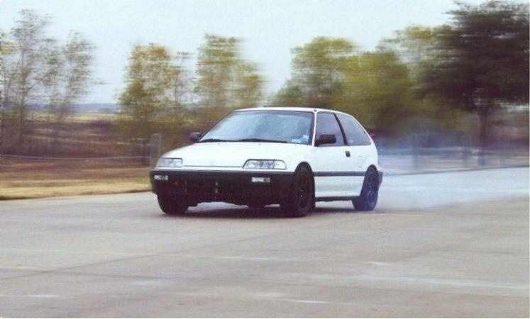
While still running well with oil pressure that’s unchanged from the day the engine first fired, over the last couple years, I’ve felt that the engine was beginning to labor a bit running through the upper-gears, indicating the ring seal was going away (single compression ring pistons). I built this engine in 1998, so I feel like it’s served me quite well, but now it needs to rest. We removed the supercharger system from the car last year to more readily replicate it for a few old friends’ D Series engines…..and while the Civic’s not running bad, it’s certainly not the car it was with the blower system. The ITR’s performance has definitely convinced me that the Civic’s next powerplant would be based on a B Series Honda engine.
I have a number of modifications I’ll be making to the Civic, which as many of you know is my favorite car of all time.Aside from the engine, these changes include major steering/suspension/chassis upgrades configured to make the car even easier for this old one to drive.Since the Civic’s engine compartment has never housed a B Series drivetrain, there are a host of new components necessary to make the swap a success. Rather than trying to re-engineer a mounting system, I elected to purchase the mounts and cable/hydraulic clutch conversion from Hasport. I don’t think there’s any question that their kits are the best in the industry, as is evidenced by the number of companies who copy their components.
My steering rack is 16 years old, and while it’s not presenting any problems that I’m aware of, I’ve elected to fully rebuild and install a Quaife rack and pinion to reduce the number of turns lock-to-lock. I realize that with the additional weight of the B Series drivetrain the steering effort will be increased, but having wrestled many “muscle cars” with manual steering in the past, I figure it won’t be too bad. In addition to a few quarter miles, I plan to run laps at the Motorsport Ranch’s road course, so the reduction in steering turns will be welcome.
As for the transmission, I feel that the gear spread of the ITR transmission should work out well for the Civic with it’s relatively short tires, however, I’m not too keen on the engine RPM required to run 70mph on the freeway in fifth gear, so we’ll “fix” that. I purchased a new ITR gearbox from the local dealer several months ago, as well as a LS fifth gear set to keep the revs down. The Honda ITR limited slip will be replaced by a Quaife differential for more precise control of torque and piece of mind from a reliability standpoint.
The clutch is a twin-disk ClutchMaster piece featuring their “green” friction material to permit a bit more-friendly slippage than is possible with the ceramic combination in the ITR.
The twin disk unit can be shifter cleanly at high RPM (over 9K) and it has less plate pressure than I’d need with a single disk, and that’s important when you’re looking to extend the life of your thrust bearings. The entire package (clutch and flywheel) is also extremely lightweight, which allows the engine to rev almost too quickly (I’ll address this later). I’ve relied on ClutchMaster’s clutches exclusively since purchasing my first one in 1996. Their clutches have consistently held up to all the punishment I’ve been able to dish out, and as many of our customers know, I use what I sell.
Connected to the transmission (literally) is the shift linkage. I’ve used B&M with a stick extension in my cars since 1997. The extension has been necessary to get the shift knob closer to the steering wheel for more convenient access. Even with the extension on the Civic, I still feel like I’m reaching a bit, especially on 3rd to 4th and 4th to 5th gear shifts.Right now my plan is to cut the tunnel in the car and splice in a few sections of steel to “raise” it higher, allowing the entire linkage mechanism to move upward as well, moving the shifter to a position that’ll make gear changes as effortless as possible.
While we’re still on the driveline end of things, I’m using a new set of DriveShaft Shop Stage 3 axles and hubs to insure that there’ll be no breakage problems. I’ve chosen these axles because over the past couple years, I’ve seen a lot of our engine customers who’ve opted for cheaper axles that ended up being a waste of money in the long run. Age has taught me to save my money and buy the right parts (once) and satisfaction will me mine.
My current shock/spring combination consists of Koni double adjustable shocks with Eibach springs I’ve “customized” to suit the Civic’s current weight distribution and driveline. After looking very closely at all the possible combinations available, I’ve elected to have the folks at True Choice Racing Koni Shocks custom-build a new set of Koni double adjustable coil-overs for me using Eibach springs with rates that are considerably different from my original combination..
All of the suspension’s (old) urethane bushings will be replaced with (fresh) ones. The front cross member will also be replaced in order to make room for the HyTech Exhaust header. I’ve procured a tubular cross member from (full-race) which use spherical joints at the ends of each traction bar end to eliminate the flex common with rubber or urethane strut rod bushings. These bars also allow precise setting of front-end caster.
I’m an advocate of running all of the factory splash-guard covers to keep debris out and radiator air flowing properly, so we’ll be building a number of supports for their attachment. I’ll also be looking at possibly installing a front engine mount connected to the cross-member.
As for the radiator, I’m not a big fan of the mini-twin core units, so I may have a custom (stock width) aluminum radiator built for the car that’ll provide good header clearance using twin cooling fans.
Around back, I’m debating swapping my rear control arms for a set of CRX units with disk brakes (I’ve had them for 3-years), or possibly just going with FastBrake’s rear disk conversion kit. At any rate, I’ll go with the combination that's lightest and most cost-effective.
Now it’s time to discuss what’ll make it “go”.
The ITR’s B Series engine has been an impressive piece since day one. It’s torque and drivability continue to astound me, and with it’s 13.4-1 compression ratio, it also achieves outstanding fuel mileage which is becoming more important by the day.
These dyno charts are from the sister engine to the ITR’s 2-liter, which is identical in every aspect. I should also note that this engine has seen over 150 dyno pulls, including many brutally long ones used during a tuning classes that we hosted. Despite the fact that the block is just a posted B20, the engine’s cylinder leakage is less than 1.5% in every hole at TDC and mid-way between TDC and BDC….which is impressive.
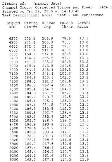
For years I’ve told enthusiast’s that RPM stands for ruins peoples’ motors. It was true back when I was building kart engines, and it’s still true today. Since my Civic is my everyday workhorse, I want the engine to last at least five years with the only maintenance being oil changes and an annual valve lashing before I drive it to the dyno for state emissions inspection.
In an effort to make more power at lower RPM, I decided some time ago to stroke the engine I build. Having built a number of 95mm (89mm is stock) combinations, I’ve concluded that while they may be great for drag racing where the owner is committed to frequent maintenance, the bearing/cylinder wear I’ve observed is simply not acceptable for an engine I’d install in my own vehicle.
On the other hand, we’ve built a lot of engines with 92mm cranks over the last couple years and when coupled to a 5.531” rod, the bearing/cylinder wear is so acceptable, that we typically have the Crower cranks, custom Crower rods, and our Roller-Wave pistons for the combination in stock at all times.
I designed a set of 85mm pistons with a 4.3cc dome for my engine almost a year ago, and we even machined a Golden Eagle block for them, but after months of soul-searching , I decided that I’d either use an ERL-sleeved block, or just go with a Dart block and be done with it.
Endyn is now a Dart Machinery WD, so the combination I’ll be building is based on a stock deck-height Dart block with an 85mm bore diameter. The block came with an 84.5mm rough bore, and I’d have stayed with that smaller bore, except I made the pistons a year ago at 85.0mm, to be used in GEM sleeved block. My experience with the Dart’s has been that 85mm works quite well for all NA applications, as well as most turbo engines, despite what Dart says.
Prior to machining the Dart block I had Mike weld many of the deck coolant passages, as well as extending the edges of the deck on the exhaust side. I don’t like leaks, whether they’re water, oil, or compression, and after a close examination, I found that on the corners, the block’s deck simply doesn’t extend far enough outboard to give adequate crush to the head gasket’s embossed rings around the large oil return passages. While some may never have issues with this, my experience has always been that if a problem can occur, it’ll always do so, especially on something that belongs to me…..
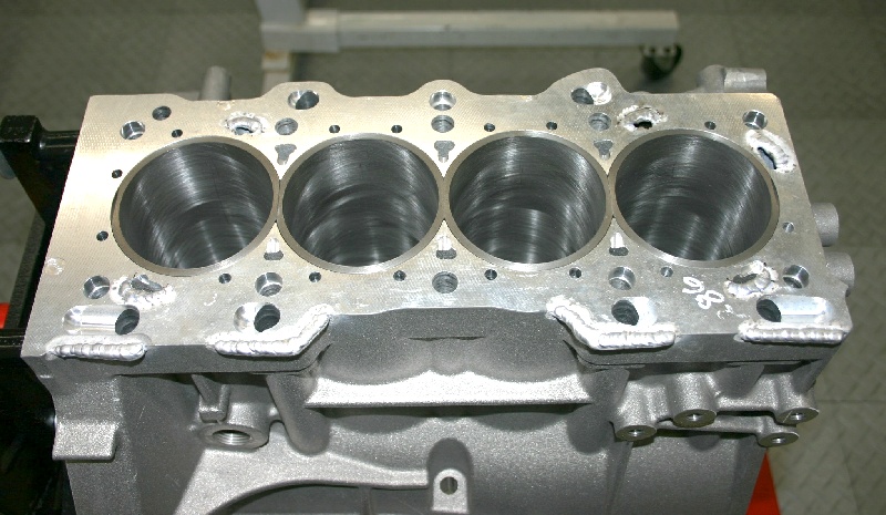
I also took a careful look at the passages that transfer coolant from the block to the head and discovered that they aren’t as properly aligned (as I’d like to see) with the holes in the head gasket, or the GSR head itself. Since good cooling is essential, especially on a high compression engine running marginal-quality fuel, we “fixed” the problem by moving the deck passages and reshaping them for greater transfer flow efficiency.
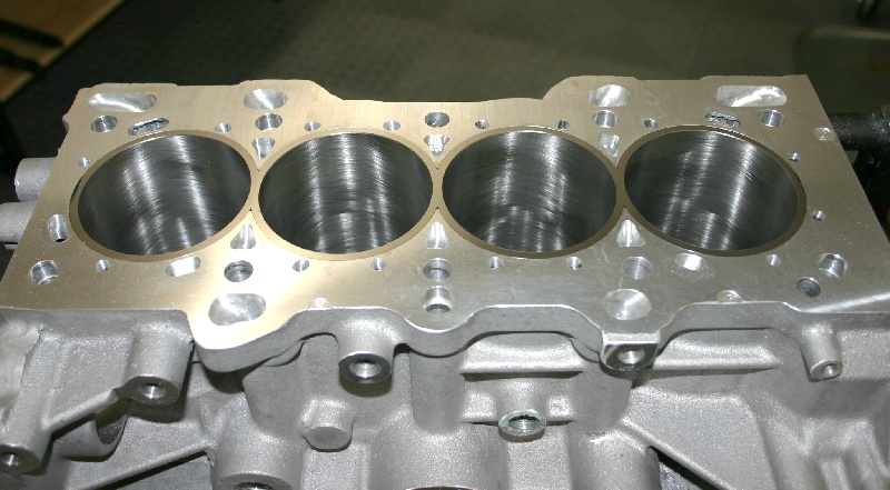
I torqued a head on the block, using an old head gasket that’s identical to the new one I’ll use in the final assembly, and we pushed the assembly in and out of the shop several times a day for a week, letting Mother Nature “season” the block a bit to insure that everything was properly “settled”.
After all this, we finally bored and honed the block (using a torque-plate and appropriate head gasket) for the 85mm pistons, setting clearance at exactly .0030” with no more than .0001” taper or deviation in concentricity where ever measured. All of the machining was accomplished with a torque plate and head gasket in place to properly “distort” the cylinders.
We also removed the main caps, re-torqued them in place, and lightly line-honed the main bores to insure that everything as straight and true.
While the Dart blocks are sturdy pieces, the casting quality certainly isn’t “Honda”, and there’s a considerable amount of deburring, passage cleanup, and casting smoothing necessary to bring them up to the standards I demand here. It took me approximately a day to get everything sorted out to the extent that I’m comfortable with all the surfaces that will be exposed to oil, either directly or indirectly.
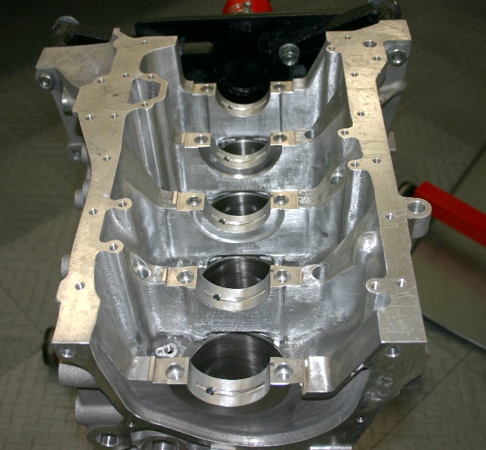
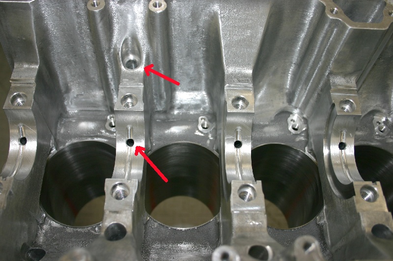
Aside from radiusing every "edge" in the crankcase, I also polished and enlarged every oil passage and drain-back passage in the block. Note the larger and chamfered main bearing oil feed passages.
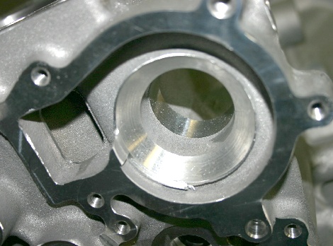
The Dart block has a lot of "rough" edges everywhere you look, as evidenced by these pictures of the water pump housing and the block's passage that normally houses the black breather canister.
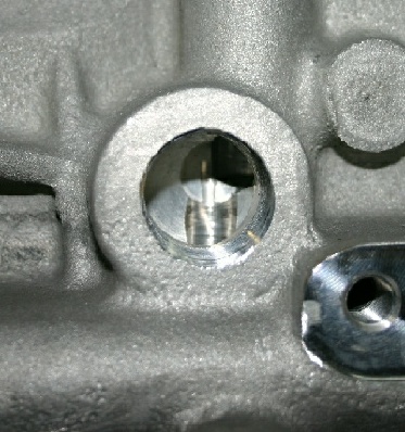
Note the oil drain-back passages consist of passages that are simple drilled intersects.
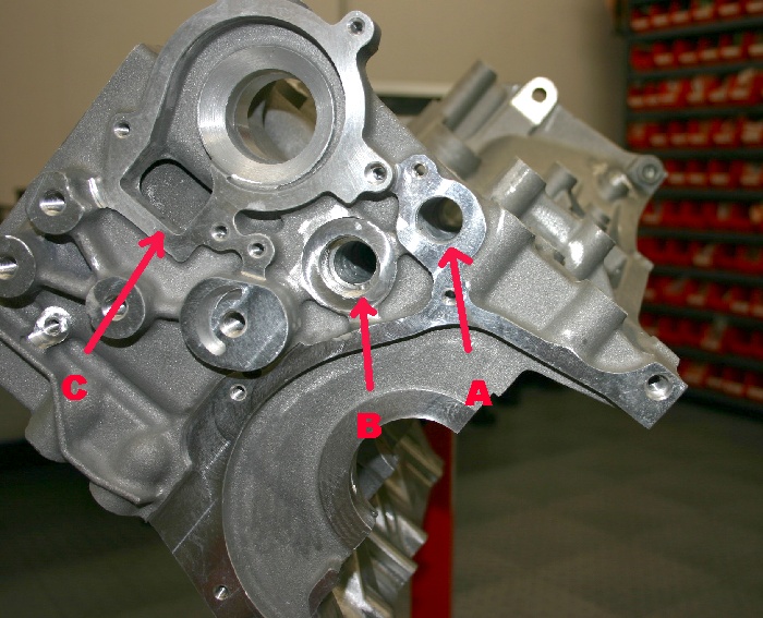
In the picture above, we've enlarged and polished the oil feed passage (A) by .250" from the front of the block all the way to the oil filter housing. The main oil galley (B) has also been polished internally, and the water pump housing (C) has been thoroughly deburred.
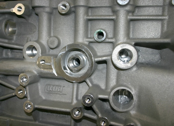
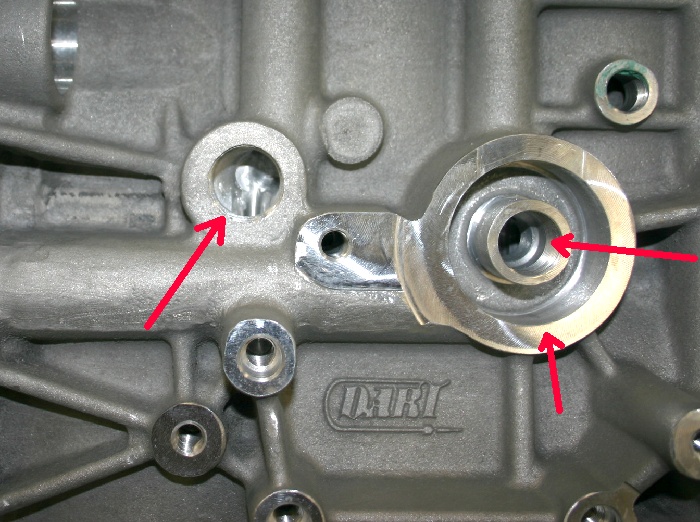
Note the larger oil passage feeding the oil filter housing and the enlarged and radiused oil drain-back passage intersects in the two pictures above..
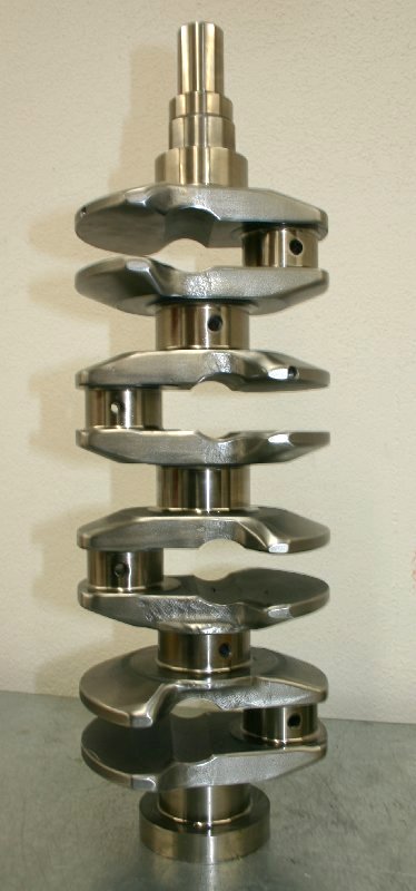
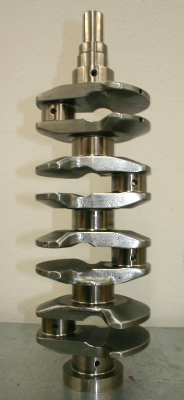
The crankshaft is one of Crower’s excellent forgings, which I had delivered with slightly wider counterweights than their standard issue pieces. Obviously, the wider counterweights have more mass, so I’m sure that many of you are wondering what’s going on here. Actually, it’s pretty simple. Driving my ITR with the 2-liter engine and the CM twin disk clutch isn’t as easy as I’d originally anticipated. With the engine’s compression, the throttle response is too sensitive with the low clutch / flywheel mass, and pulling away from a stop is difficult to accomplish without tire-spin. This new engine should be even more responsive, so I’m going to try to increase rotating mass a little to lessen it’s sensitivity to tiny throttle inputs, especially off-idle. In the pictures, you can see that I spent several hours re-shaping the leading and trailing edges of the crank’s counter weights to approximate an airfoil (large round leading edges, and tapered trailing edges) in an attempt to reduce crankcase windage.
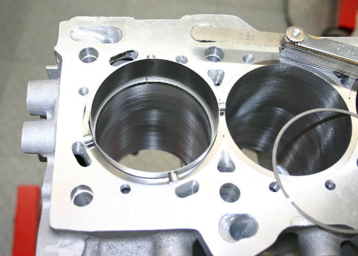
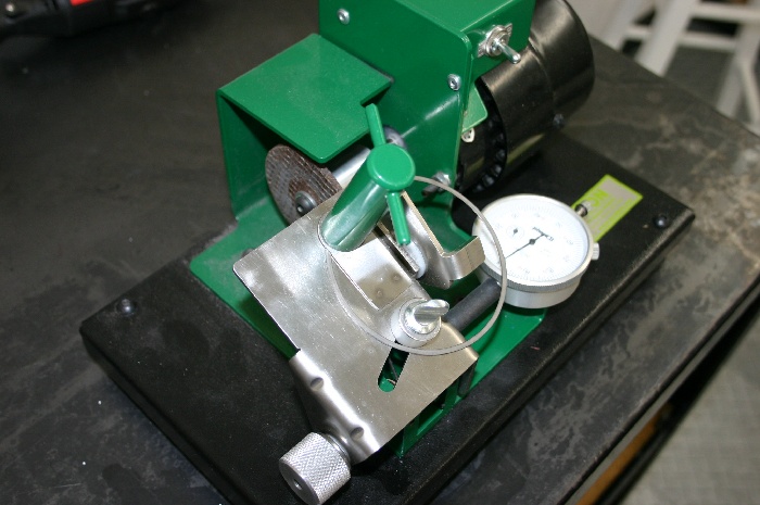
This machine's a lot easier on my old eyes than using the Dremel and a cut-off wheel for machining end gaps. It's also more accurate. It's still necessary to use a small stone to deburr the machined ends of the rings to remove any edges that might hang in the ring grooves, or score the cylinders.
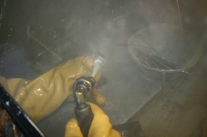
Before any assembly takes place, each and every component is thoroughly cleaned in our Pro Ultrasonic cleaning machine to insure that there's no foreign material hiding anywhere. After the ultrasonic cleaning, we use the water-blast cabinet for final cleaning. I also used soap, hot water, various brushes and sponges on the block.
Assembly begins here.
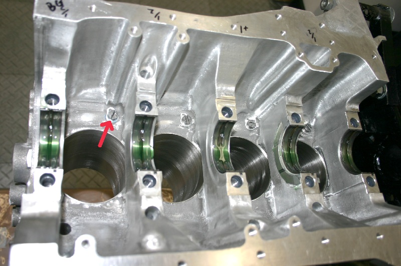
We've fitted the block for RSX main bearings at clearance of exactly .0015". I also machined and installed some screw-plugs to block off the oil squirter passages which will not be used in this build. Note that we've lubed all the bearings thoroughly.
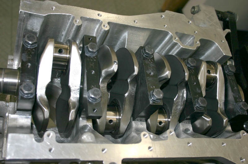
The main bolts are torqued in three steps to 65 ftlbs using moly lube on the threads, as well as under their washers and heads. Note the tapers on the crank's leading and trailing edges.
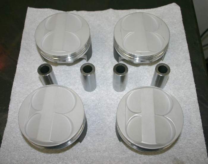
My pistons are the same mid-dome pieces we use in customer engines and sell to the public. They feature 4.3cc domes, .993" compression height, strutted skirt design, and weight of 260gm. I've customized these with lateral gas ports, a dry-film skirt coating, and a ceramic dome coating. Piston to wall clearance is exactly .0030".
After hone-fitting the pin bushings, balancing, and fitting bearings (.0015" clearance), I used our water-blast cabinet for final cleaning of the rods and their bolts.
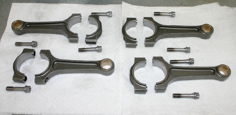
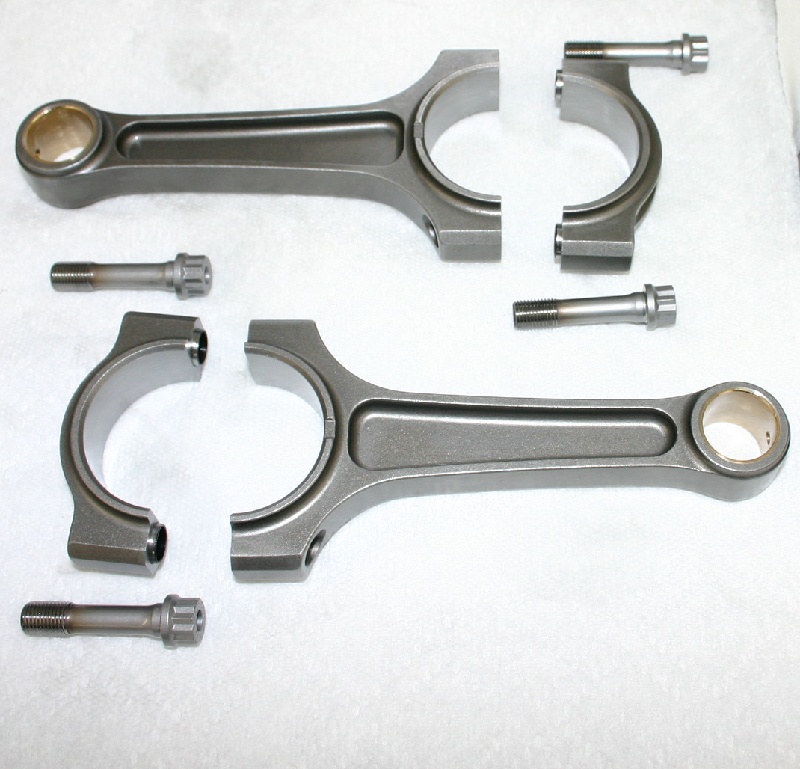
The rods are the same pieces we sell our customers. Crower custom builds these 5.531" long super-lightweight pieces for Endyn with their best 3/8" bolts. They aren't cheap, but you don't have to worry about them every time you buzz the engine past 10K either. We hone their pin bushings for an exacting pin fit and we check their balance before a thorough cleaning. I use Crower's lube on their bolts.
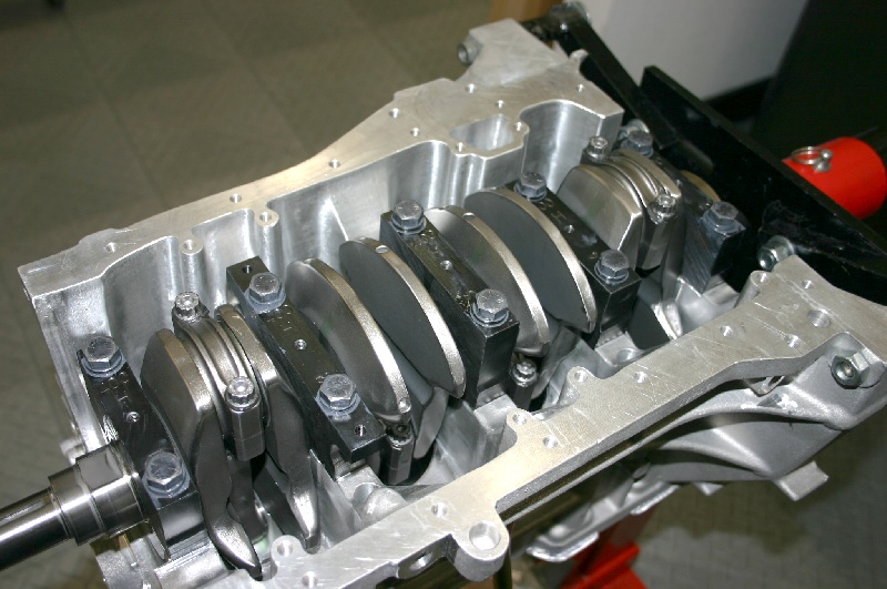
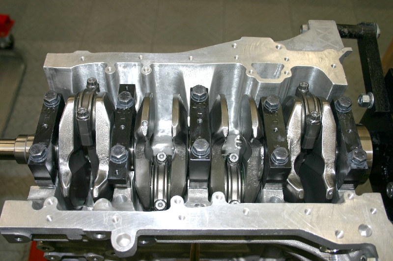
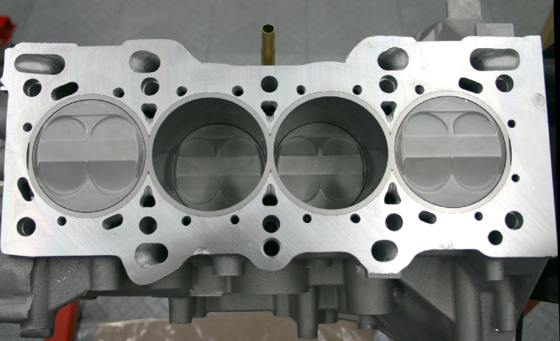
Once we install the modified ITR oil pump, rear main seal, and the modified Canton oil pan and windage tray, the short-block's finished.
Now we'll switch to the cylinder head for this project. I originally purchased this GSR head from Acura way back in 1997 and it's been sitting around patiently waiting ever since. The modifications will be the same as the "pinch-head" CNC ported pieces we offer the public. While the modifications were developed for use with a 34.0mm intake valve, I'm sticking with a 33.5mm valve for more mid-range torque on this street engine.
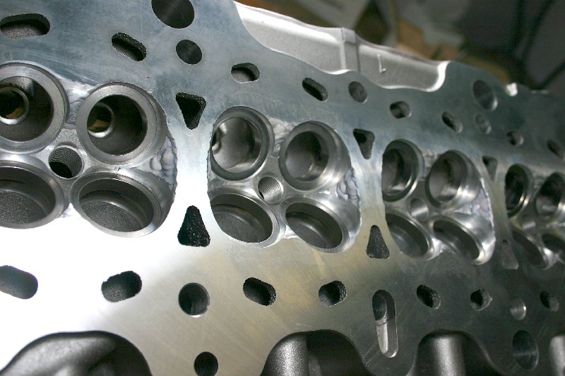
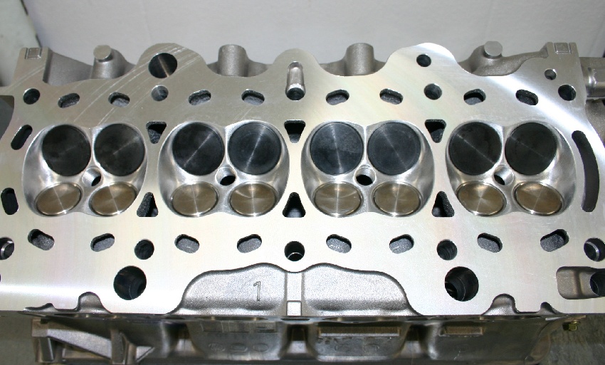
As you can see, the headwork begins with welding the chambers. I've already installed the larger-than-stock Dura-bond valve seats in this picture. These seats are deeper and larger in diameter than the factory pieces, increasing stability substantially.
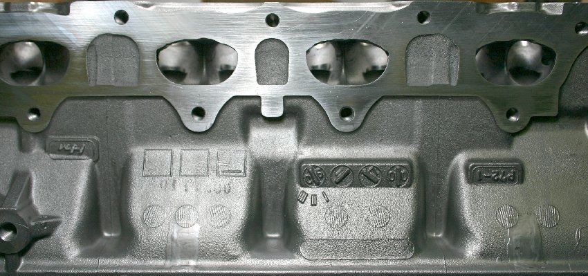
Note that we've welded the floors of the GSR's exhaust ports, as we want them high enough to allow us to use our B16 CNC ProStock porting.
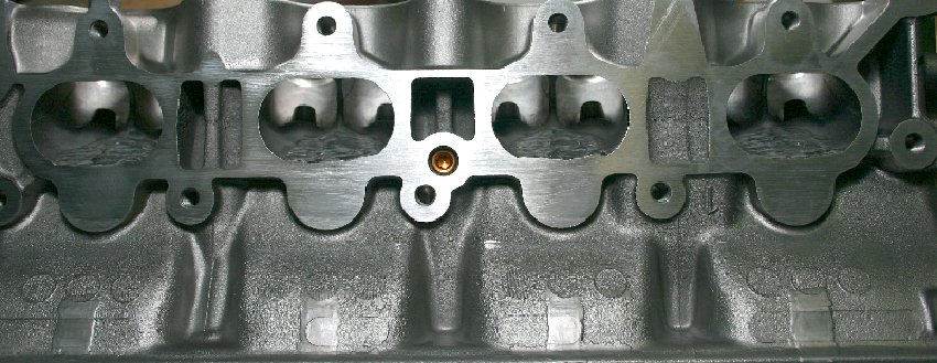
We also welded the intake's roof's and injector slots to eliminate some of the wasted area that's present in the stock head.
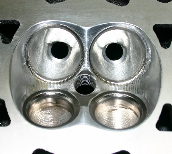
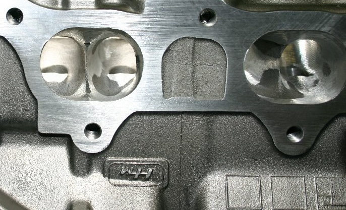
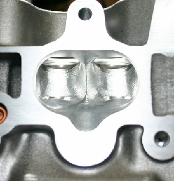
The raw CNC chambers and ports are in the pictures above. Note that on the exhaust-side, there are a number of areas of the ports that aren't touched when machining our B16-style ports in the head. The port roof and injector slot design we prefer is much lower than in the as-cast GSR port.
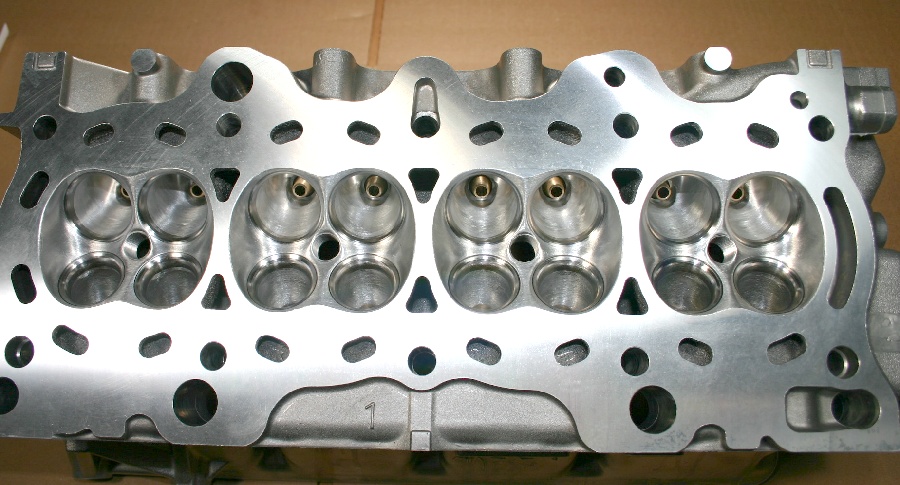
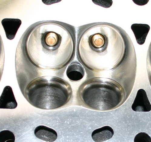
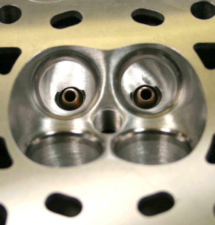
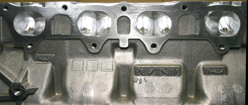
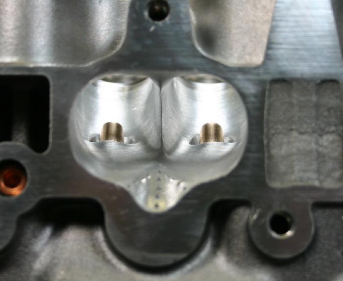
Modifications to the head after the CNC porting consisted of installing some specially-tapered manganese-bronze valve guides I spent a couple hours making as small as possible, some port and chamber smoothing, as well as a finish valve job. I've milled the head to net stock valve to deck clearances, which resulted in a chamber volume of 41.3cc's. With .010" deck clearance and a .030" Cometic head gasket the static compression equates to 13.21-1, which I believe (from my experience with the 2-liter in my ITR) will be manageable on pump-gas.
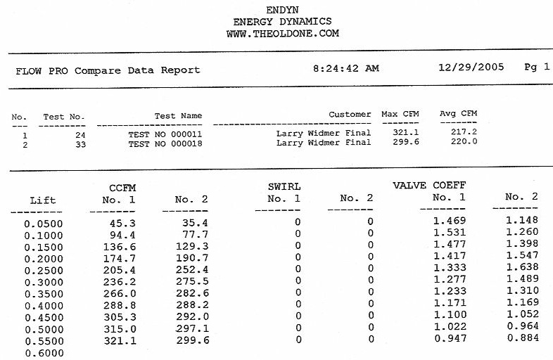
Here are the "Superflow" numbers from the head. Pressure drop was exactly 28". I'd post my more-meaningful quality and pulse cfm numbers, but they'd just give some people something to complain about....
As you can see the head's no slouch, and just as with a couple other engine combinations I've built over the past few years, the cam timing will be radically-different on each side. Keep in mind that I've configured the ports, to make big power without screaming the engine unmercifully and running cams with less duration and less lift fits right into my game-plan.
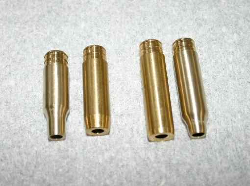
While on the subject of the head, I've rounded up a picture of the valve guides. The guides as we purchase them are on the inside of the picture. From an airflow standpoint, whacking the guides off flush with the port roof's would be optimal, but shortening valve guides is just bad business as far as I'm concerned. In order to maximize valve stem / guide life with high-lift cams and valve springs that have significantly more pressure than stock, the guides must be as long as possible. We normally machine these guides with a straight taper to reduce their cross-section and I also widen the port roof slightly to compensate (area) for the space they occupy in the port. As you can see from the guides on the outside, I've machined a radius that connects the diameter of the guide body to a radically-reduced guide diameter that will occupy as little space in the port as possible, while still lending full support to the valve stems. With this guide configuration, I was able to keep the port a little tidier, netting a small gain in airflow.
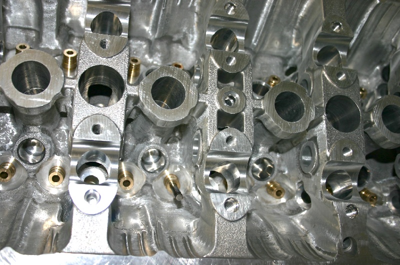
I'm using our oil plumbing kit to push more oil to the top of the head in an effort to reduce valvetrain wear. To insure that the drain-back to the pan is as efficient as possible, I also spent some time grinding on the camshaft-side of the cylinder head. This particular head casting was as "nasty" as any I've ever seen from Honda. There was an exceptional amount of casting flash and casting roughness. The drain-back holes were also not as clear as I'd like, so here's the result....
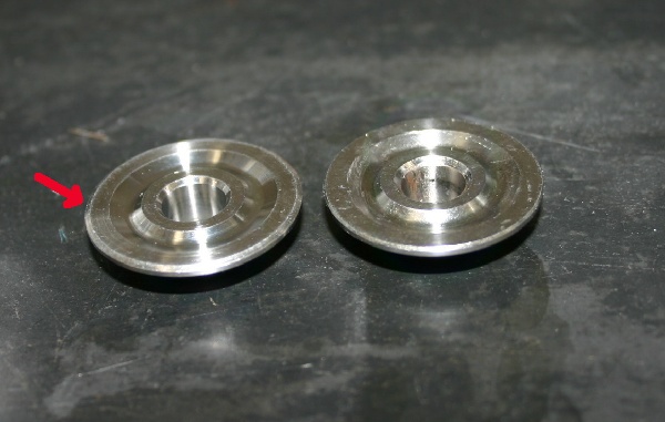
Other valvetrain bits and pieces include machining a chamfer on the outside upper portion of our titanium retainers to obtain a little more rocker arm clearance.
Last year we conducted some back-to-back oil system tests with a couple 92mm x 86mm engine combinations. In back-to-back tests, we found that there was absolutely no power gain when switching from one of our modified ITR oil pumps (in conjunction with good wet-sump pans) to a Petersen dry-sump set-up. Our pump actually pulled a few more ponies up to 9500 RPM, when the dry-sump finally pulled even. We've also run tests with the Moroso dry-sump system, and once again, there was no gain.
During my life, I've seen more than a few engines that were destroyed when dry-sump belts that departed company with their pulleys. I'm configuring this engine to be a dependable street powerplant, and worrying about an oil pump belt failure, just doesn't fit into the picture.
My oil pan of choice a year ago was the Moroso aluminum piece. We're welded some additional baffles in those pans and they've worked well in both drag racing and road racing applications. The baffles we've fabricated prevented the oil from climbing out of the sump under high-G environments. The Moroso pans also netted a few more HP over factory pans....including the Mugen offerings. About a year ago we purchased several Canton pans after seeing them first-hand at the PRI show. These pans are of steel construction, so cracks aren't as likely to develop (as with aluminum pans), and we've found a little more power with their windage trays over the factory Honda pieces. Unfortunately Canton doesn't yet make a windage tray for use with block girdles, but we've also modified them to work in those applications too. Of course, the Dart block I'm using doesn't have a girdle, so I'm using the standard Canton tray with a little "sharpening". The Canton pan rails also will not clear the bearing support for the drive-shaft on the driver's side of the transmission, nor will it clear the transmission support castings, or the flywheel/clutch dust cover. Another point of interference is the corner of the pan's sump with John's (HyTech) large tube header's primary pipe. As you can see in the pictures, we modded the pan rails where necessary, and cut small "hunk" out of the sump and replaced it with a triangular piece of steel sheet welded in place. The dust-cover also required some mods, just like the one on my ITR's 2-liter combination. I might mention that all of these modifications have been standard-issue on customer engines we been building for the last year, so none of this is any surprise to us.
During the last 45 or so years fooling with "special" engines, I've come to find that there are very few "store-bought" parts that will fit without some massaging. Making all the pieces work together is the key to building well performing engine combinations. There are no tricks, but attention to detail is what makes all the difference.
I'll be adding to this article as time permits me to work on the engine. I'd like to have it completed and on the dyno in another couple weeks (as customer work permits), so bare with me. The Civic's also very anxious for it's new blood transfusion....
The Civic's In The House
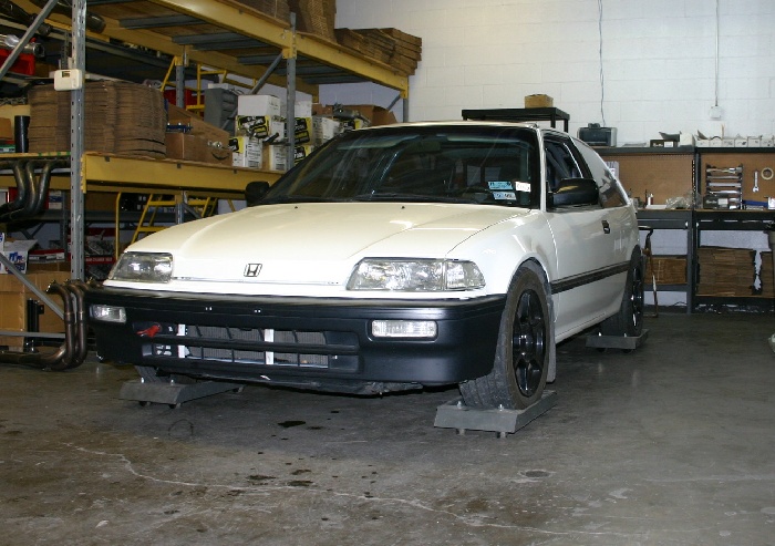
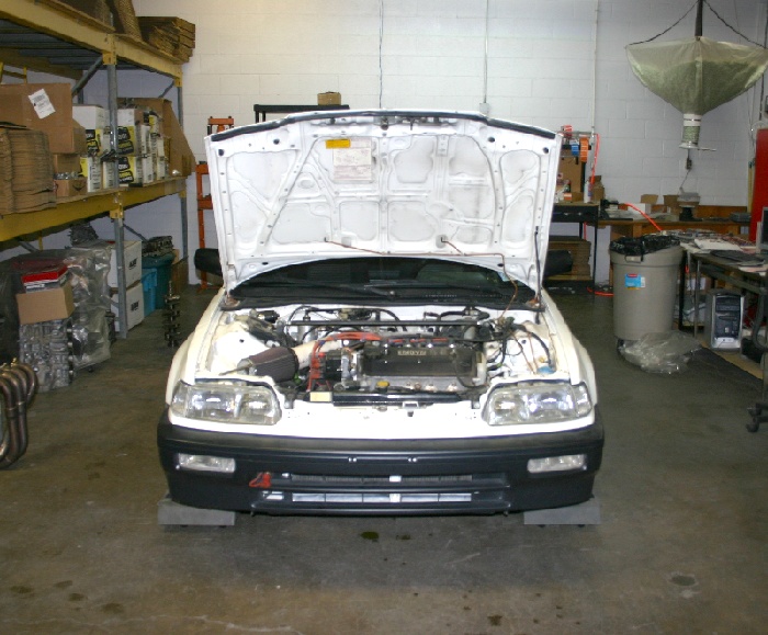
As of today, here's where the project stands, beginning with the Civic's modifications. The D series engine was removed and the engine compartment cleared out a bit. We put a head on a B series block and bolted up an "empty" B series tranny for fitment purposes.
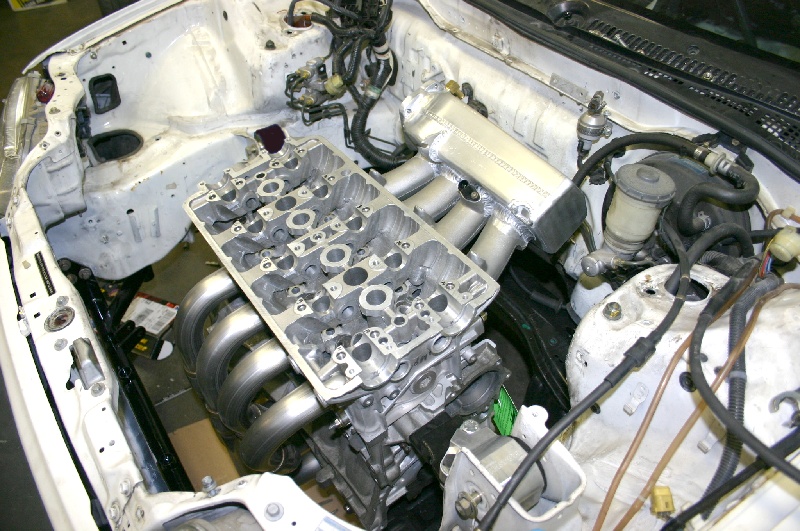
The Hasport mount kit placed the engine perfectly, netting a lot of intake manifold clearance in the rear, and the HyTech raised-port header has more than adequate clearance to the front. The Full-Race cross member was a good fit, and the only mods I plan for it will be the addition of some welded-on tabs for attachment of a sheet-metal pan, replacing the factory plastic pieces. I've also found that the Civic's stock radiator will fit nicely, but there's no room for the cooling fans, so I may use a couple 10" aftermarket pusher fans up-front. With the dummy driveline in place, it was time to address moving the shifter upward (placing it close to the steering wheel).
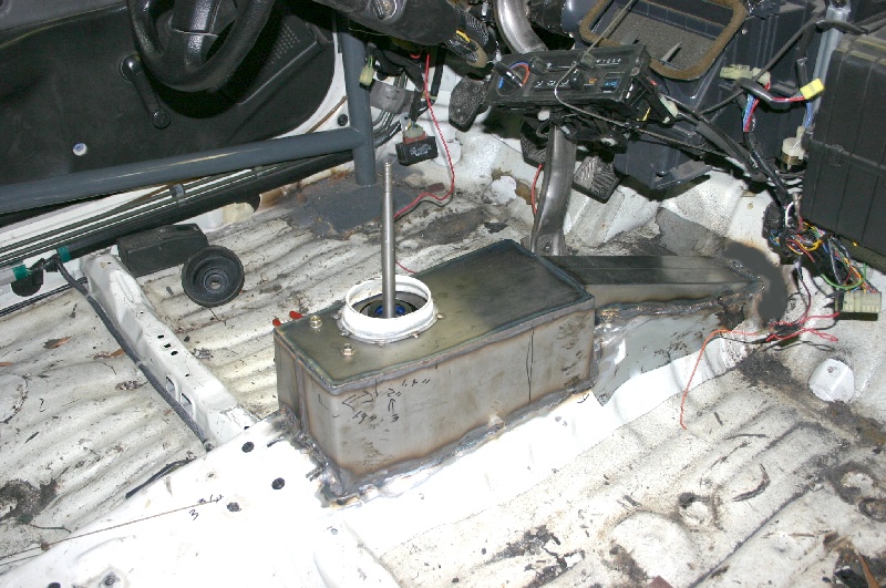
As you can see from the picture, this has been a rather involved project. After cutting the area around the shifter out of the tunnel, we had to cut a trench to allow the shifter arms to come up past the stock sheet metal. Next, we fabricated a piece that serves as the housing for the shift arms, and finally the "box" that houses the shifter mechanism. We'll fabricate the top by breaking edged all the way around, so it'll slip over the sides of the box. Mike Garvie did his normal excellent job of welding all of it in place. While everything's apart, we'll go ahead and remove some of the excessive sound-deadener from the floorboards, but the heater, etc will all remain in the car. When I was young, driving without heat in the winter was OK, but I've got to have heat and a defroster nowadays.
Engine Progress
We polished the tops of the valve springs before assembly.
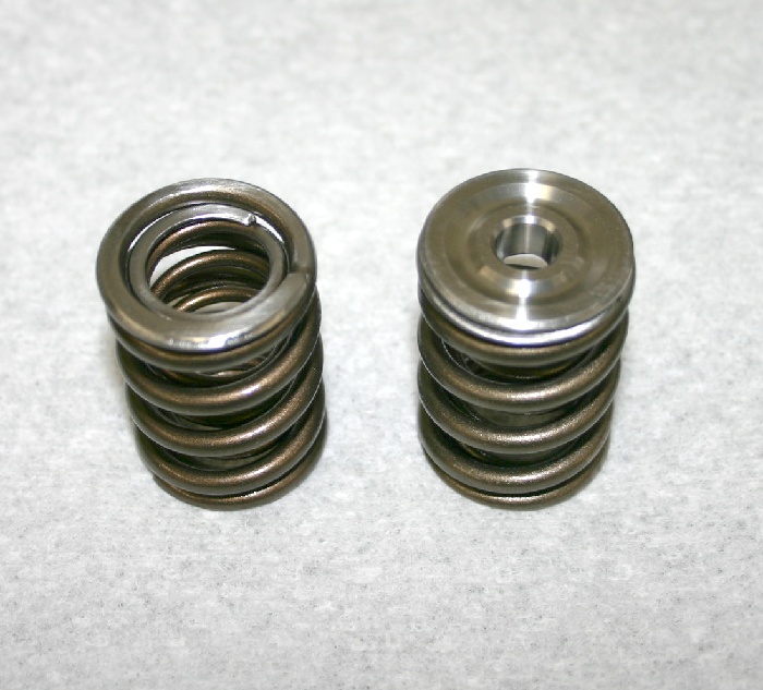
Rocker arms were clearanced just as with the ITR's 2-liter and the head was assembled.
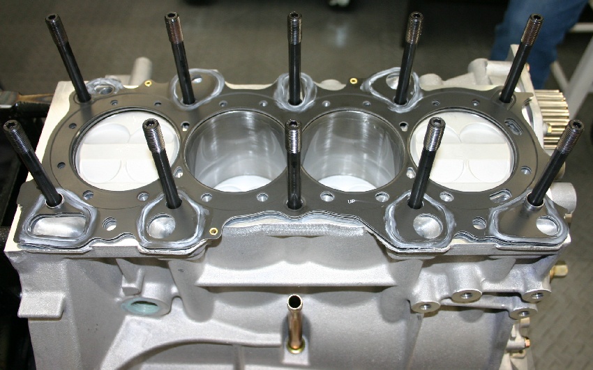
ARP studs were installed in the block, and I machined .090" from the block-dowels that locate the cylinder head. As stated previously, we're using a laser-cut Cometic head gasket that's .030" thick. We still apply a very thin coating of Hondabond to the areas of the gasket where oil flows to prevent the possibility any leaks.Both the deck surfaces (block and head) were cleaned thoroughly with acetone before assembly.
With the head torqued in place, the rocker arms, and camshafts were installed.
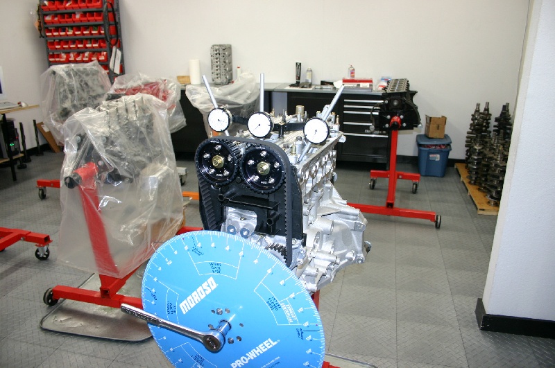
We still use my "home-made" indicator stand for setting cam positions. This is a very important step and should never be omitted from any engine-build where internal components are in close-proximity.
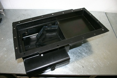
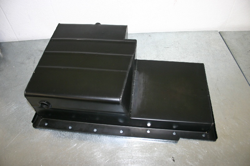
Our modifications to the sump's internal baffling and the windage tray make this oil pan combination even more efficient. We finished it up with a black zinc coating for rust-protection, efficient temperature radiation, and good looks.
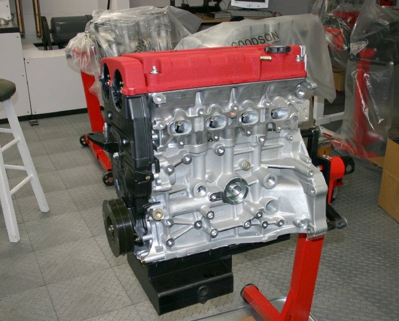
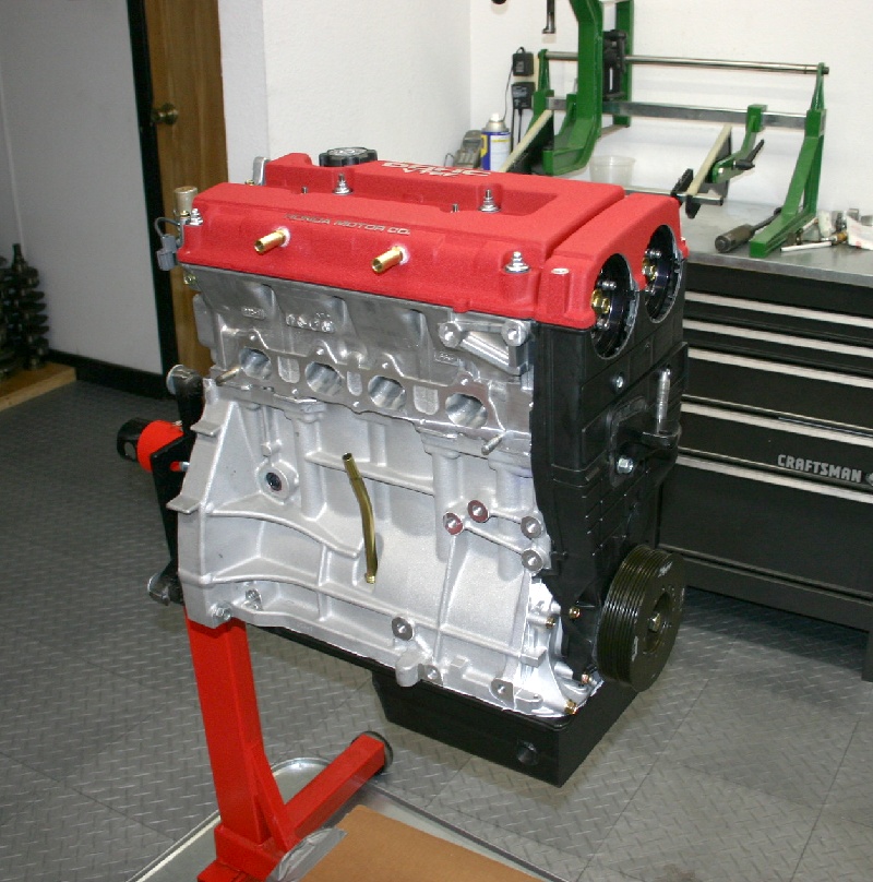
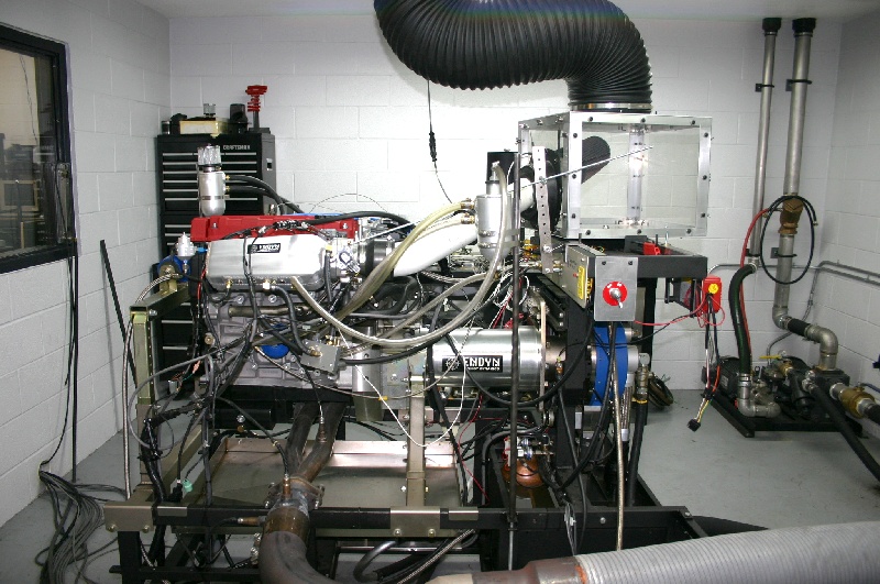
As you can see the engine's buttoned-up and ready for the dyno. We'll plug the remaining oil/water holes and (hopefully) begin breaking it in Monday or Tuesday. This past week's been consumed working on components that go on the car itself.
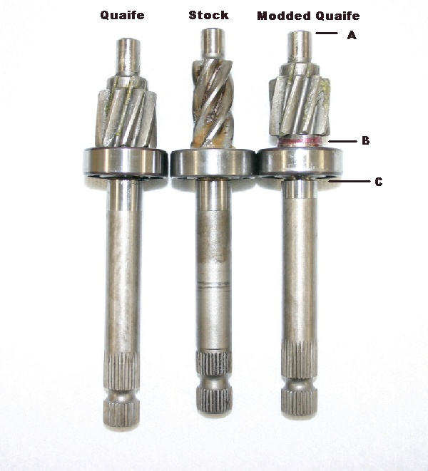
As I stated before, one of the modifications I'm making includes the installation of the Quaife rack and pinion gears to speed-up the steering. As it turns out, Quaife machined the pinion gears for use in HF and DX rack's....so it doesn't fit the Si rack. In the picture above, you can see the stock pinion in the center, with the (as-is) Quaife unit on the left. The rack rides exactly in the middle of the pinion, and you can see that the Quaife would only have partial gear engagement . To optimize the Quaife, placing the rack's gears in the middle of the pinion, I first shortened the shaft's end by exactly .085" (A). Next I machined a steel spacer, tapering the end that 's next to the pinion gear to insure that there'd be no interference with the rack's gears (B). The final machining operation (C) was positioning the new snap-ring groove that positions the spacer, retaining the bearing. I'm pleased to say that the steering action is very smooth. If you're getting the idea that there's no such thing as "bolt-on" parts, you're right. At this level, you've got to be prepared to each and every piece that goes into the combination....if you want it all to work trouble-free.
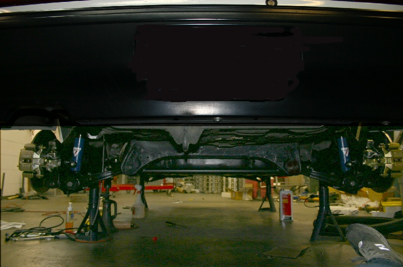
One of many modifications I've made to the car's chassis includes welding plates to the rear cross-member, and then welding in a tube connecting them. This should help reduce flex between these two suspension pivot points for improved handling.
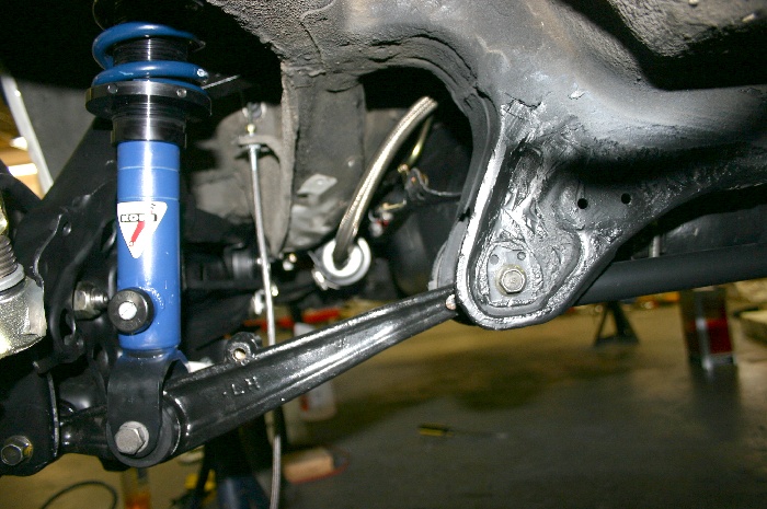
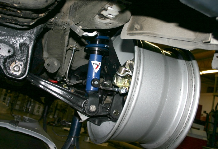
All the bushings in the rear suspension were replaced with black urathane components. I drilled radial holes in the large bushings installed in the trailing links to encourage them to be more compliant. Heavy-duty adjustable upper control arms and heim-jointed front toe links from SPC are also in use. The shocks are custom Koni double-adjustable coil-over's that folks at True-Choice built for me.
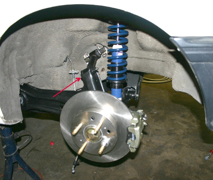
Rear brakes, just as the fronts are by Fast-Brakes. Their kits fit perfectly, and as far as I'm concerned they're the best bang-per-buck on the market. One of the modifications I plan in the future includes the use of wider wheels with 225 x 45 x15 rubber. Note that I've removed pie-shaped slices from the outer corners of the upright and repositioned/welded the material so it's closer to the upper-link's bushing. This increased the clearance to the inside of the 15" wheels by another .400", which should pay some benefits when I go with the wider wheels. At any rate, thinking ahead and modifying the components while everything's apart can certainly make life easier later on.
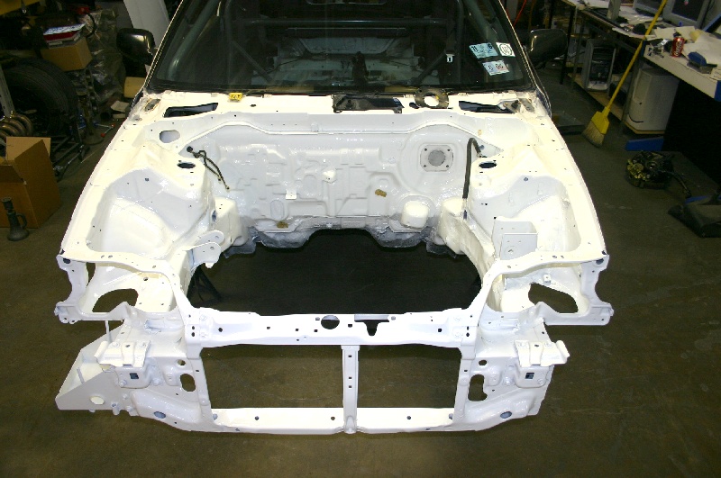
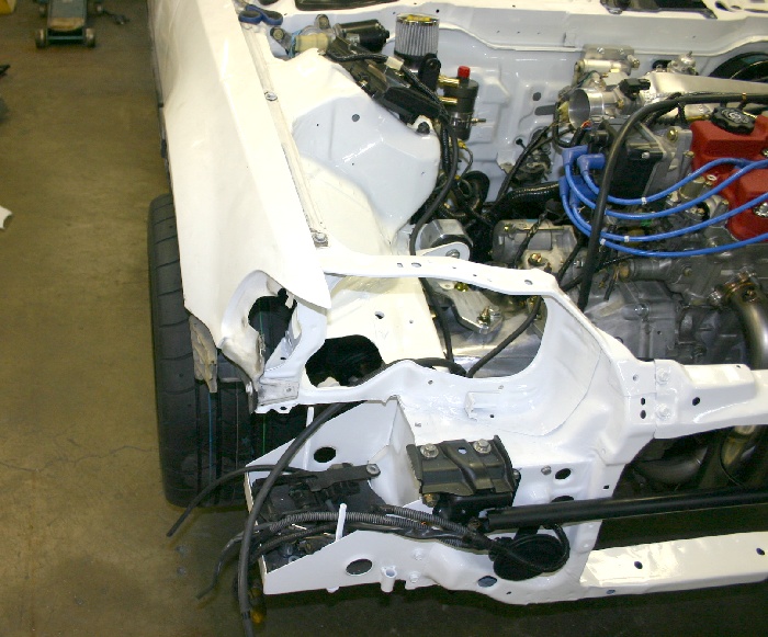
Up front, we completely stripped the car, cleaned it, and treated it to a fresh coat of Polar White urethane paint.
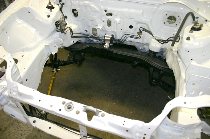
The modified rear cross-member has been reinstalled with the Hasport mount, the brake lines are back in place, and the Full-Race front cross-member has also been bolted in.
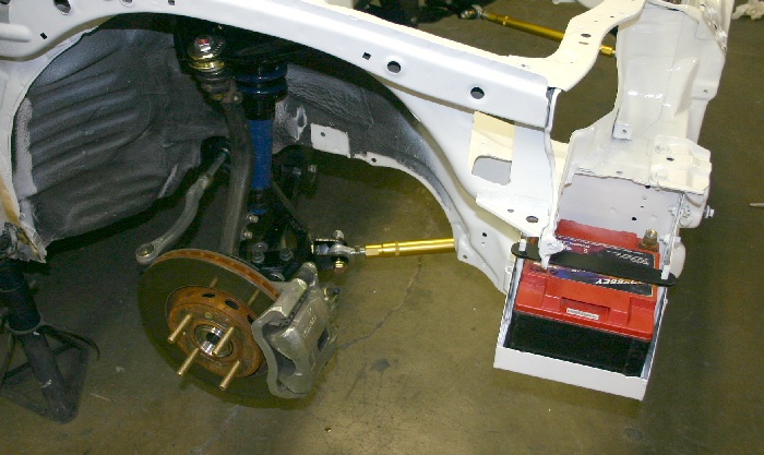
The SPC ball joints are installed in the upper A-frames, the True-Choice Koni coil-over's are in place, and the battery's back in it's box, which positions it's weight as far forward, and as low as possible in the chassis.
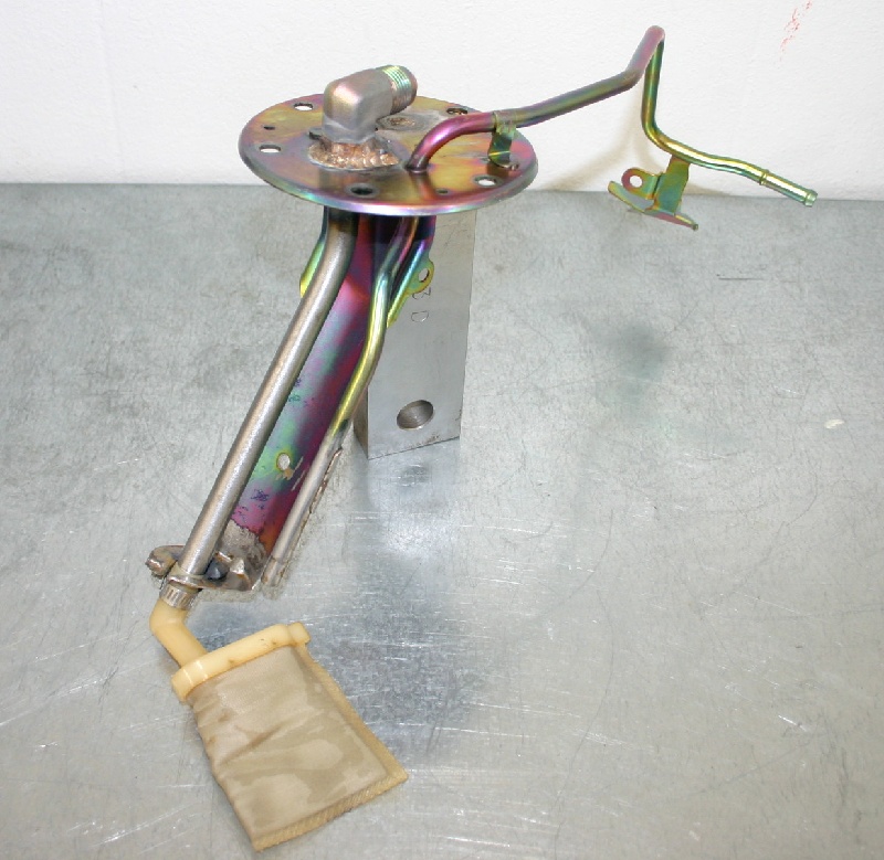
Work on the car so far this week has consisted of routing the -8 fuel line and condensing the wiring harness. We have (finally) completed the dyno project we've been working on for the last month, and the Civic's engine is on the pump and ready for break-in.
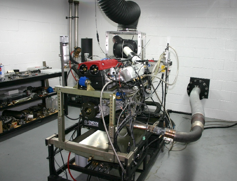
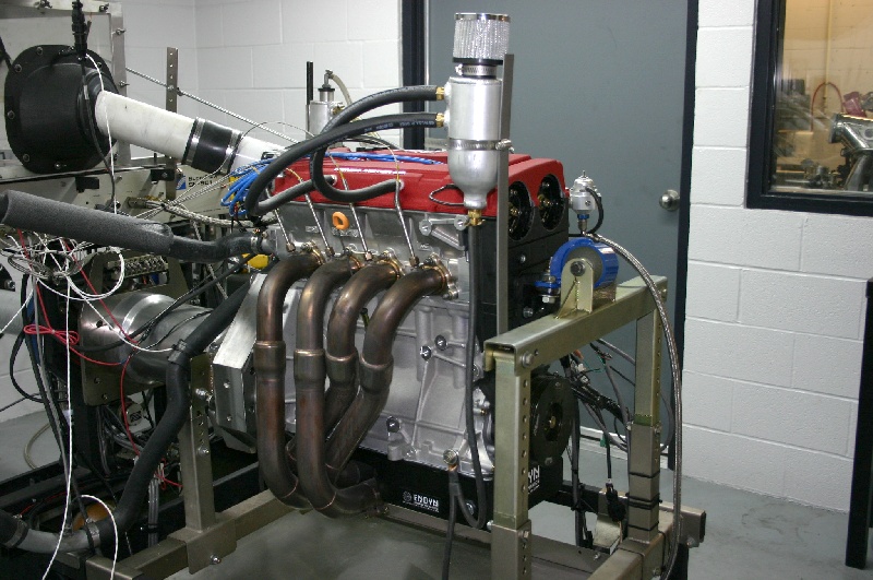
We started the engine Saturday and my ears were greeted by excessive mechanical-sounding noise coming from the #1 cylinder area. Run time was less than one minute, and on the console, all vital signs had appeared good. On removing the valve cover, milky-looking oil was everywhere, so we immediately knew that water had found it's way into the crankcase somehow. A subsequent leak test revealed that when #1 cylinder was filled with compressed air, there was a gurgling sound in the water tower. Once the head was off, we found some rust in cylinder #1, and a pin-hole in the cylinder liner. See the pictures below.
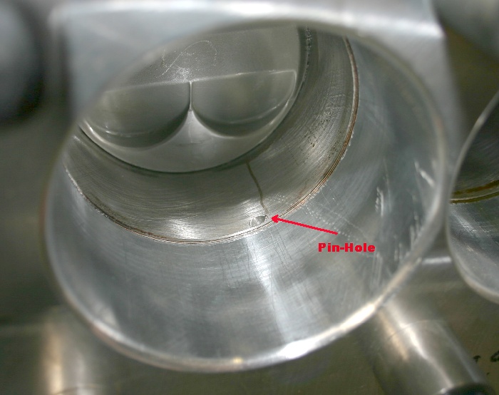
We've installed out torque plate along with the Cometic head gasket. The block is laying on it's side, and the only pressure on the cooling system is from gravity. The tiny pin-hole is visible, as is the water coming out of the hole. Also, note the trail (marking) the water's path down the bore and the attendant rust elsewhere in the cylinder. Since the sleeves in these blocks are supposed to be "dry", I'm not sure how this leak is occurring, but it's obvious that there's plenty of porosity in both the aluminum block casting as well as the cylinder liner. I'll be talking to Dart about it first-thing Monday morning.
The block arrived at Dart today. It'll have it's sleeves removed to find out how the water has migrated through the aluminum. Assuming that part can be repaired, they'll re-sleeve it for us.
A careful component examination has showed that starting the engine was an expensive proposition. The rod in #1 is "tweaked", and the crank has a .002"bend in it. I've just about used up my window of opportunity for this project, as I've got to spend more time cranking out heads and customer engines, so for the time-being, the plan is to assemble an existing sleeved Honda block that's already been fitted with some of our mid-dome pistons. I'll use a crank that's similar to the one in the ITR's engine (B18A/B that's been lightened a bit and balanced, along with another set of our Crower lightweight +.137" rods. I'll still use the head intended for the Dart engine, along with a fabricated manifold that has slightly longer runners for more mid-range torque. Rebuilding the Dart combination will just have to wait until I have more time....and right now, that looks to be a while. We pressure-test all the sleeved blocks we machine, so we'll also be doing the same testing on the Dart's in the future.
02-11-06.... All's being taken care of with the leaking block. Bud (at Dart) is handling everything to my satisfaction, so we should have that combination alive and well again in another week or two.
We've fitted bearings to a new set of rods, on a new crank for the "temporary" engine. I have some oil pan mods to finish Monday, but that's all that remains other than assembly. I have to spend full time on some K Series heads for a few days, but Josh should have the engine completed and bolted to the dyno by mid-week....assuming our head gaskets arrive when they're supposed to. Speaking of head gaskets, Cometic informed us that they're no longer making HP series gaskets....so it looks like we'll be "O" ringing most of the heads we're doing in the future.
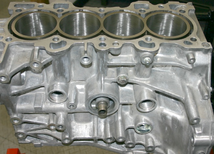
This block's had a LOT of time on it's clock, so I'm pretty confident that it'll be stable. It'll be interesting to see the power differential between it and the Dart combination when it's together again.
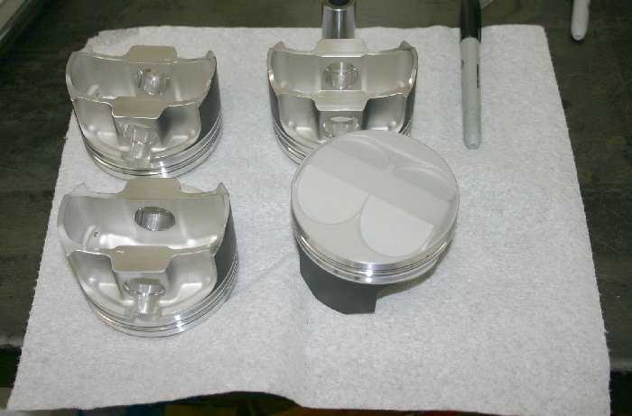
Pistons are from the same batch that were used in the Dart block.
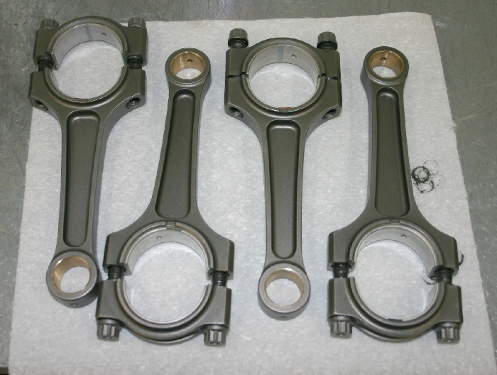
The rods are the same dimension Crower pieces, but we machined a little more from the sides of the small-ends, reducing their weight by 10grams each.
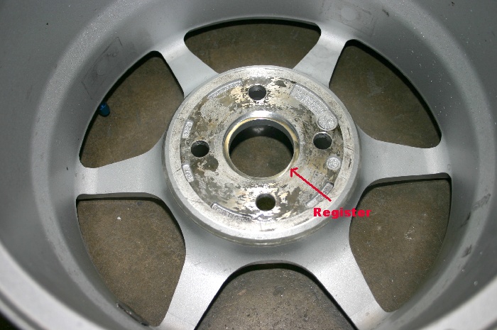
Progress on the car has been steady. I received the 8" -wide Kosei's from a friend. The wheels were intended for a Miata, so the back spacing and the hub-centering diameter needed some attention. We made some .200" thick aluminum wheel spacers that are an exact fit for the hubs on the car.
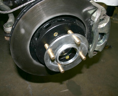
The spacers center on the hubs, and in-turn have a hub that fits into the register we machined in the wheels. See below:
As you can see from the pictures below, the car's got some serious wheel width now......
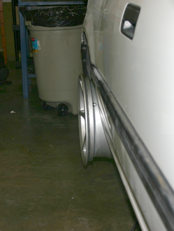
If everything remains on schedule, the wheels should be power-coated my mid-week, and my tires (Toyo RA1's 225 x 45 x 15) should be heat-cycled by then as well. It looks like it's porta-power time for the rear fenders, as they need to "expand" another 1.5", to cover these things!
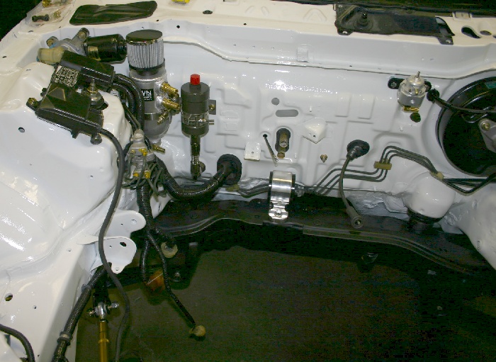
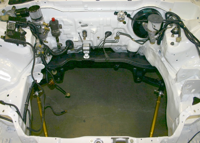
Up-front, I've remanufactured the wiring harness, condensing it into a much simpler affair than what the factory provided. The new brake booster and master cylinder are in place, as it the rear breather tank, -8 fuel line with Kinsler fuel filter, speedometer cable, clutch cable, throttle cable, and regulator. We've also reinstalled the heater and ducting, steering column, and pedals. The dash is also ready to slide in place, so the car's coming together nicely.
It's Saturday, the 18th, and we've put approximately 4 hours on the engine. We're being extremely careful with it so far with spark timing that's between 24 degrees at low rpm and 14 degrees in the upper ranges. The highest RPM we've run is 8000, and VTEC has not been enabled. The engine's making 177 ftlbs by 4900, and it's airflow limited to 210HP which it carries from 6400 to 8000 RPM. Other similar combinations we've built have wanted VTEC at 4600 RPM, so there should be a huge jump in the power numbers ahead. Before knocking off for out usual Saturday afternoon hamburger treat, we leaked each cylinder and smiled.......all four are 1%...or less!
02-20-06 We spent about a half hour fooling with the fuel curve in VTEC this morning. This is the one and only full pull we did. I was pulling back on the throttle at 9000 RPM.
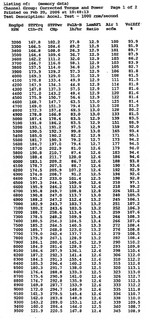
The combination we ran consists of the sleeved 85.0mm block, with the lightweight 5.531" rods, 92.0mm crank, our mid-dome Roller-Wave pistons, the welded GSR head, our Bump-Stix intake cam, a 1997 ITR exhaust cam, our valvetrain components, one of the fabricated manifolds, a 65mm Edelbrock throttle body, one of John's Hytech big-tube headers, stock GSR distributor, and Hondata S200 for tuning. Running 92 octane, the engine showed absolutely no signs of detonation, so I think we could definitely add a bit of timing here and there for more torque, and there's no question that there's more available once the fuel curve is cleaned up. I also think a larger throttle body is in line, but I'll save that test for the chassis dyno where I'll be doing the final tuning. Right now, we have to get the car out of the shop as quickly as possible because our Fadal 5-axis is ready for delivery, and the car's occupying it's space in the shop.
We disassembled the ITR transmission and installed both the LS fifth gear and the Quaife differential prior to bolting up to the engine with it's ClutchMaster's twin disk clutch and flywheel combination. The combination proved to be a great fit in the car with the Hasport mounting kit.
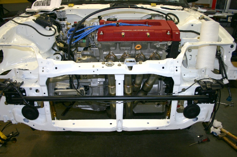
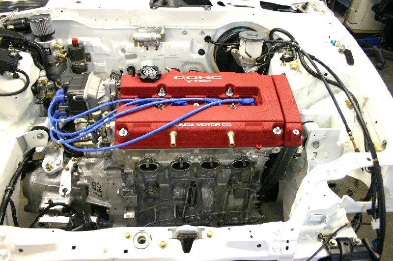
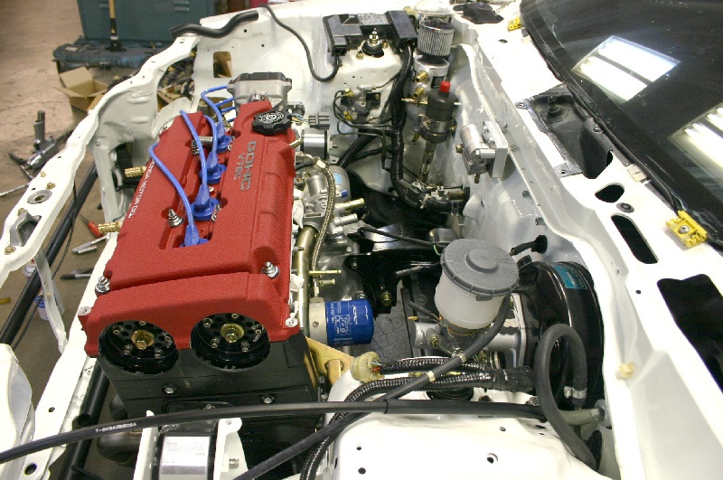
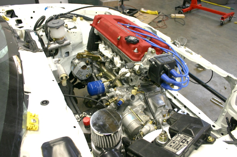
During all this, I spent some time remanufacturing the engine compartment wiring harness. Anything that wasn't necessary was removed and all the essential wiring was shortened and re-wrapped using harness wrap available from Eastwood. Next up is the clutch linkage, and getting it to work in a reasonable fashion was like pulling teeth.
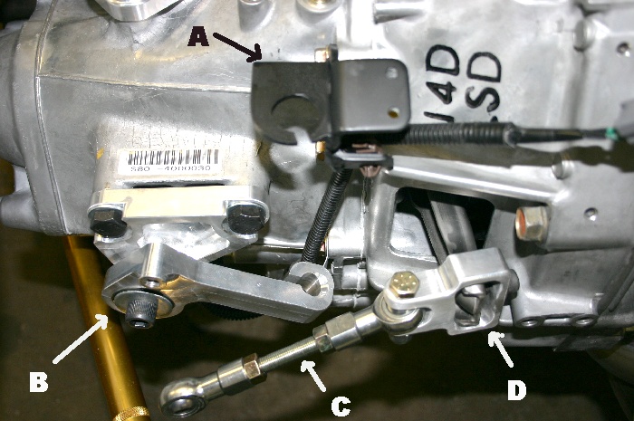
The basic problem with the cable to hydraulic conversion is one of flexation. There was so much movement in every direction that 2/3rds of the pedal travel was consumed before the clutch actually operated....and worse yet, you couldn't "feel" where the flexing stopped and the clutch was disengaging. Some of the fixes we came up with included: (A) Fabricating a steel bracket that supported the bottom of the billet aluminum upper cable mount to prevent it from bending. (B) Making an internal bearing spacer to reduce the slop between the ball bearing and it's retaining snap-ring. We also machined the arm to allow the insertion of a thrust bearing to prevent movement in planes other than the one in-line with the throw-out arm end. (C & D) We canned the Hasport billet connecting arm because it never pivoted properly on the throw-out arm and we fabricated a simple heim-jointed arm that has better freedom of movement..
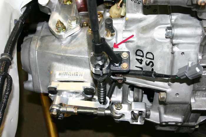
After all this, the cable flexed too much at it's upper attachment, wasting more pedal travel yet, so I fabbed a bolt-on support to eliminate it. As you can see, it captures the cable and holds in in a position where it's pulling straight on the lower arm.
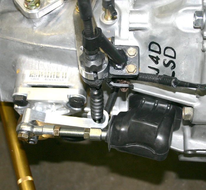
Here's the finished set-up. I purchased another cable to hydraulic conversion kit from a California outfit which was all steel in construction...and it flexed so badly that we elected to can it immediately, and not waste time trying to "fix" it. At any rate, the clutch reminds me of some poorly conceived set-up that I ran on my old Mustang in the mid-sixties....and my plan is to remove the guts from the ITR transmission and stuff them into an YS1 case I have. This will allow me to utilize the factory cable combination, which will surely solve all the problems that still exist.
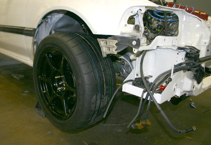
I had the wheels stripped and powder-coated black (like the old ones), and the 225x45x15 Toyo's have been heat cycled and mounted. As you can see, the stock front fenders don't cover the additional width too well....
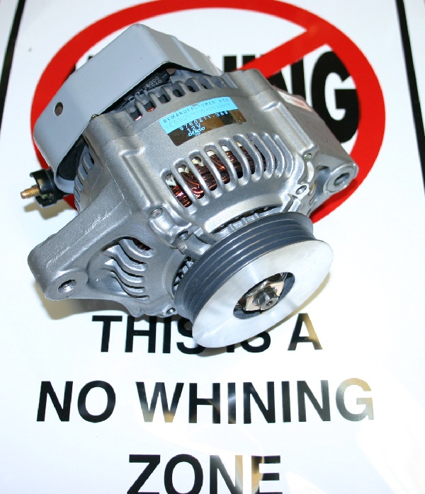
I elected to use a new D series alternator that I bought back in '98 (and never needed), as it's both physically smaller and lighter than a B series piece. This required a few mods to the mounting brackets. In an attempt to reduce alternator RPM, I machined the outer pulley section off one of my alternator pulleys (from the ill-fated B series supercharger system, and bushed the bore smaller to fit the D series alternator shaft. The diameter of this pulley is .125" larger than any of the Honda B series pulleys, and it has larger belt-retaining sides, so it should work well.
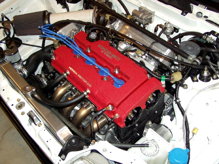
After installing the CR aluminum radiator, we started the engine and pulled it outside.
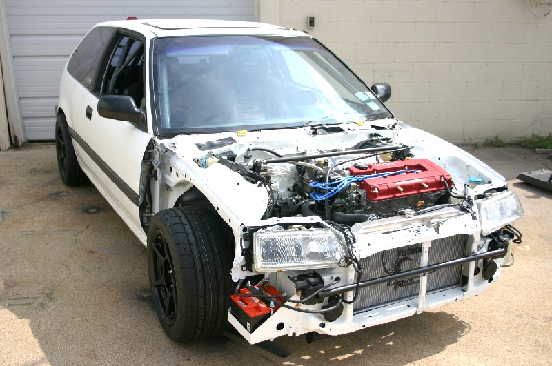
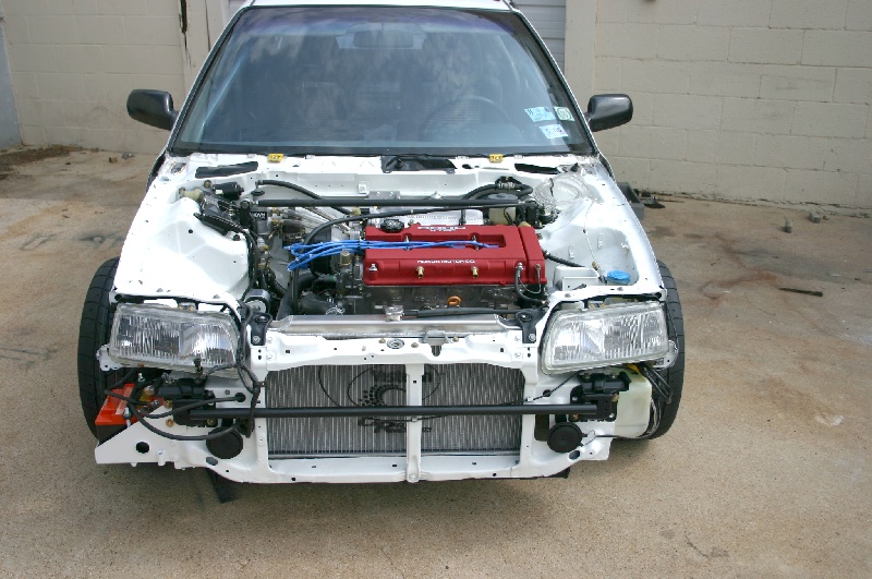
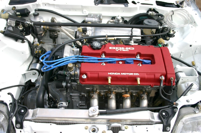
Since these pictures were taken, I put an old air cleaner and tube from the NA D series on the engine, and drove the un-aligned car to Alamo Autosports for a quick trip across the Dynojet. The chart's below:
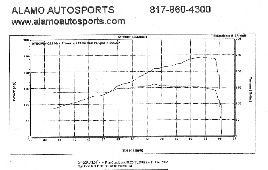
I should mention that the car was a real handful to drive, and I suspect that the additional tire/wheel friction took a good bite out of the power. Fuel was 92 octane Chevron.
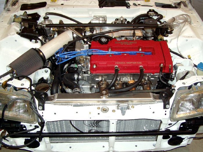
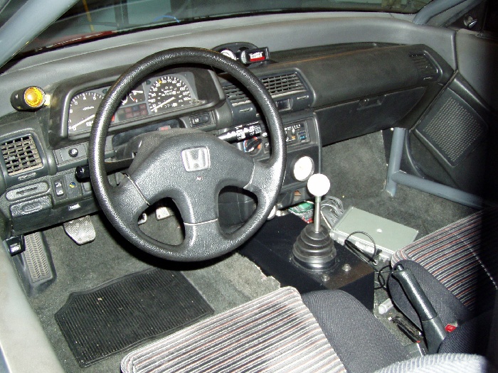
After the dyno session, I managed to talk the folks at Mac Churchill Acura into staying late so we could align the car. We "reduced" front camber to 1.9 degrees (rear is 1.4 degrees), and set the toe-in, which was really out of whack to "zero". I put 2.8 degrees of caster in the front. Man, what a difference the alignment made. The car is a dream to drive (except for the clutch action), and it really boogies in the first three gears ( I haven't had any long straight stretches available for more testing yet.). The engine's absolutely quite at idle and low throttle angles used for most everyday driving, but romp on it and it sounds like a deep-throated Japanese bike. I like it......The new shifter location works wonderfully. If you look in the picture above, you can see the wide-band O2 gauge and the MSD Knock-Alert in a housing in the dash. During the next few weeks, I'll get some front fenders on it, bolt the P72/S300 ECU under the dash, build an induction tube that'll simulate ones we've proven on the dyno, and fix the clutch situation.
5-20-06 Update
We've been so busy with customer projects that I've had very little time to devote to the Civic...other than enjoying driving it to and from work almost every day. There have been some changes I've made in an effort to affect drivability....especially in the clutch department
As you recall, I've never been terribly satisfied with the clutch action afforded by the combination of my modified Hasport cable/hydraulic conversion kit and the ClutchMaster's twin disk clutch. I've had the clutch for almost a year (saving it for the project) and nobody could remember if it incorporated the max-race, or the street diaphragm, so I had CM ship the street unit to me for a trial run. While the transmission was out, I swapped all the gears into a new YS1 tranny case I purchased new from Acura. My thinking was that the factory cable throw-out arm assembly would be superior to the modded Hasport....but it really wasn't any better. The releasing the clutch still required almost the entire travel of the pedal, with full disengagement occurring with the pedal very near the floor. This was definitely not making driving fun.
I called Chris Jewell (formerly of CM) and now at Competition Clutch. Chris sent me one of his twin disk clutch / flywheel kits. While appearing similar to the CM unit, the CC set-up uses an entirely different flywheel step and pressure plate positioning. While pedal pressure (with the street diaphragm) was still high, the clutch did provide less pedal travel for engagement and better overall drivability. The issues confronting cable twin disk users are the result of two things. First, the throw-out bearings are so large in diameter that the don't contact the inner edges of the diaphragms, but rather the middle of the fingers, resulting in poor mechanical advantage.....and high pedal pressure. Second, the distance from the rear of the throw-out bearing (where it contacts the throw-out arm) to the face of the bearing that contacts the clutch fingers needs to be increased about .100".This will prevent the throw-out arm from going so far over-center, which once again adversely affects mechanical advantage. I'm currently working on remedies for both of these problems along with Chris Jewell.
During all this, I also felt the shift linkage wasn't as (smooth) as I'd like, so I shit-canned the factory-style shift linkage and built my own from 3/4" tubing. There are no kinks or bends in linkage I fabricated and the car shifts like a "luxury car".
On the engine front, all I've done is put gas in it. We did a leak-down test on it a week ago and all the cylinders were under 1%, so it's sealed up pretty tight. I've purchased a Skunk2 70mm throttle body and hopefully I'll find time to install it in a week or so. I also plan to add about 3" to the length of the secondary tubes of the Hytech header I'm running, as I feel that this particular (experimental) short-secondary unit isn't performing as well as our trusty dyno header.
The car is a joy to drive. It accelerates just as you'd imagine a lightweight car with a big engine would. Gears one through four are brutal, and fifth is like....overdrive....making freeway driving nice at low RPM, especially compared to my ITR. Gas mileage is in the high twenties which is pretty good for a work car seeing lots of stop and go abuse, and believe me, it's also nice with the price of gas being what it currently is around here.
The car sticks like crazy with those big meats on all four corners, but it has a much heavier feel than it did with the D series powerplant under the hood. Much of this is due to to the faster steering rack which increases driver input loads combined with the castor and camber settings. The only change I plan to make on the suspension is an increase of rear spring rates, so the car doesn't squat down so much with heavy loads in the back.....remember it's my work car.
I still haven't received the CF hood that'll supposedly clear the engine's valve cover. I did take an old fiberglass hood I'd had for several years and modify it for clearance by cutting a hole in it the size of the valve cover and riveting a formed aluminum cover on it in the best traditional hot-rodding fashion.
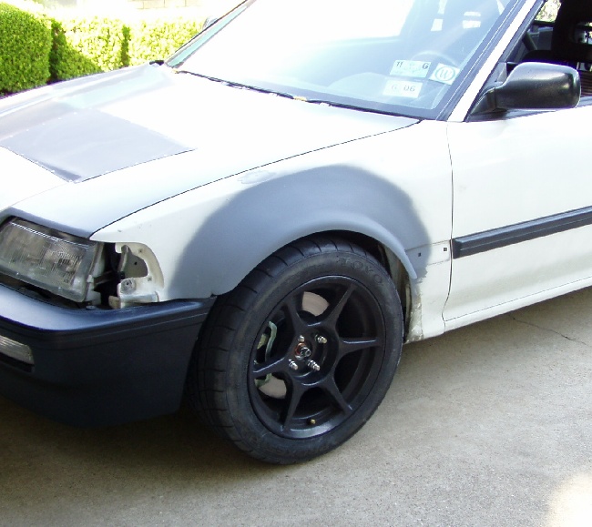
The front fenders are still in-work as you can see.
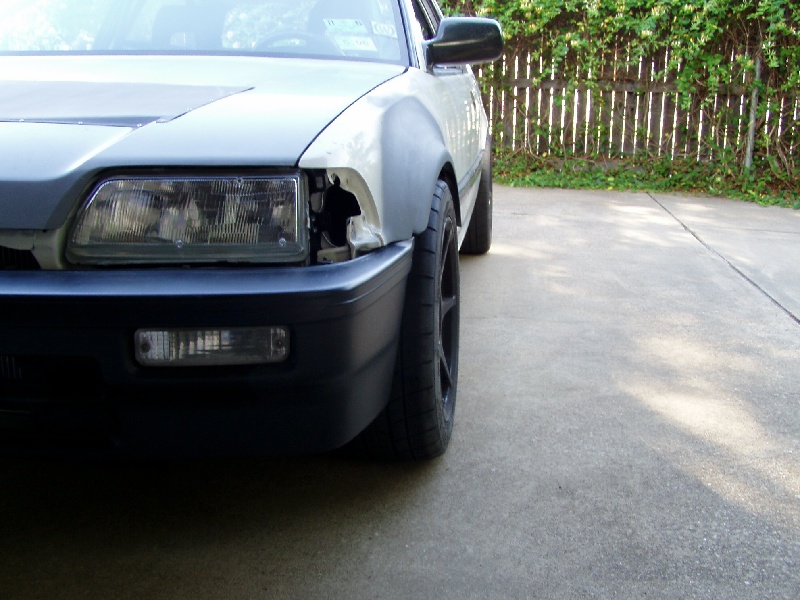
I found that the radius of 13" wheel boat trailer fenders was perfect for the Toyo's tire diameter, so after cutting a fender in half, I've welded it into the stock fender. I extended it inboard with attachment tabs so the factory plastic inner fenders would still attach providing a little more protection for the area. I originally planned to use the stock Honda fender flaps at the rear of the flares, but they don't extend far enough outboard, so they don't look all that good. My next move it to form some steel pieces that'll weld to the rear of the flares, extending them further downward and sweeping them into the fender at the bottom. I should have some time to devote to this Memorial Day weekend.
On the inside, the ECU's bolted in place under the dash. I've thrown in my well-worn Honda floor mats to protect the original carpeting. I ordered a couple Recaro Speed (Black Avus/Red) for the car about a month ago when I saw their price was going to increase. They're supposed to arrive this week and once I've finished the bodywork and paint, they'll be going in the car. The original seats are still in great shape, but the car deserves a treat for the interior so it won't be jealous of the ITR anymore......good "carma"!
So, that's about it for now. The car's happy and that makes me happy. A return dyno trip is planned once the engine's finally broken in and the header/exhaust/throttle body mods are complete with an oil change. I'll also throw one of our exhaust cams in the mix, and I suspect the resultant numbers will make some of you folks happy .......
5-29-06
I finally made time to work on the Civic today. First on the agenda was an oil / filter change (at 750 miles on the engine's clock).
Once I was out from under the car (I don't have a lift), I formed the front fender flare extensions and heli-arced them in place. I spent about an hour with some body filler doing some minor blending, and I believe that all the fenders need now is a good block-sanding prior to a coat of epoxy primer. Another few minutes of sanding should render the fenders ready for paint.
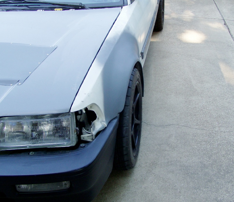
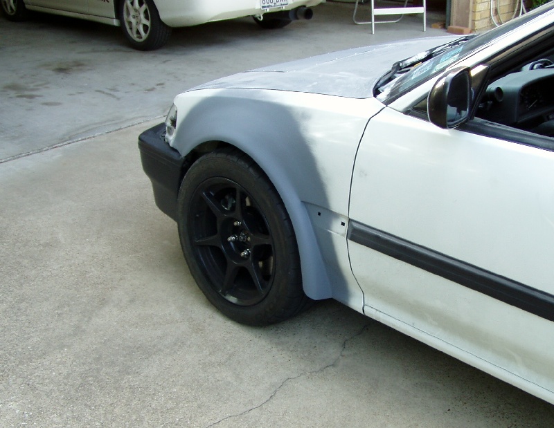
I'd like to think the front fenders will be finished (paint and all) in another couple weeks, so I can begin on the back of the car. The rear fenders won't be too easy, as I'll have to cut and raise both the outer fender openings, as well as the inner fenders before welding both into the new extensions.
When you only have a couple hours every other week or so to devote to a project, things certainly don't happen quickly. We've been so covered up with engine builds with dyno break-in's and tuning, as well as new head and manifold development programs that spending time working on the car hasn't been something that's appealed much to me. After waiting 7-months for the carbon fiber hood to finally arrive, Doug, Josh, and I were able to finish all the prep work, paint, and install all the front body pieces.
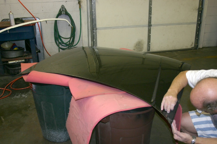
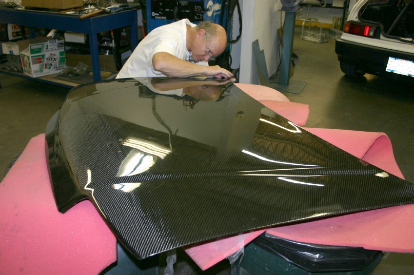
The quality of the hood was about what I expected, meaning that it needed to be block-sanded to remove ripples in the finish, and it also needed some edge-trimming to net the fit I was after. The folks at Passport JDM weren't too pleased when they found out I was painting the hood....we got a good laugh out of that!
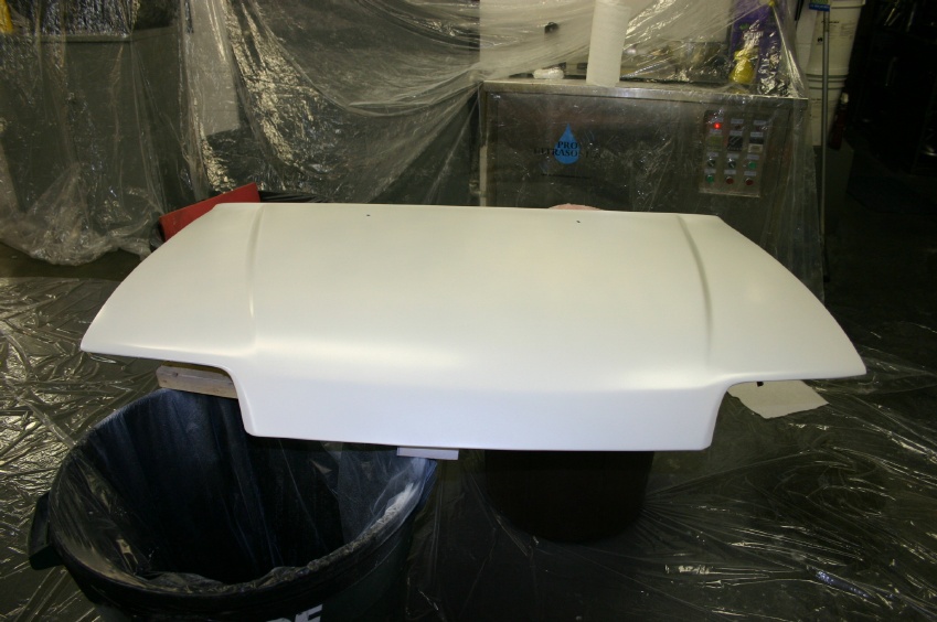
The hood (and front fenders) were all primered using a white epoxy that was sandable once cured. We were able to remove all the ripples from the hood during the process. Note the plastic tarps we used to spare the floor, ultra-sonic part's cleaner, and the side of the dyno room.....
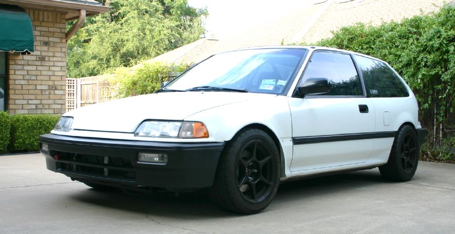
Below are some pictures of the car as it sits right now. The rubber inner-fenders and splash-shields also fit and attached just as we mocked them up, so all is good.
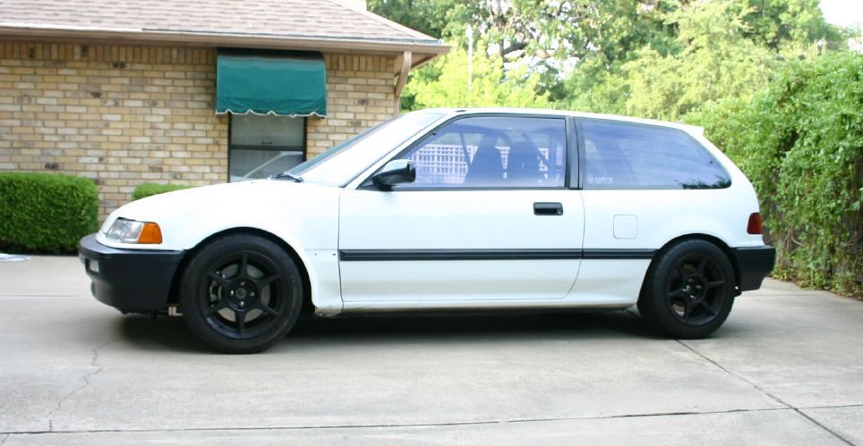
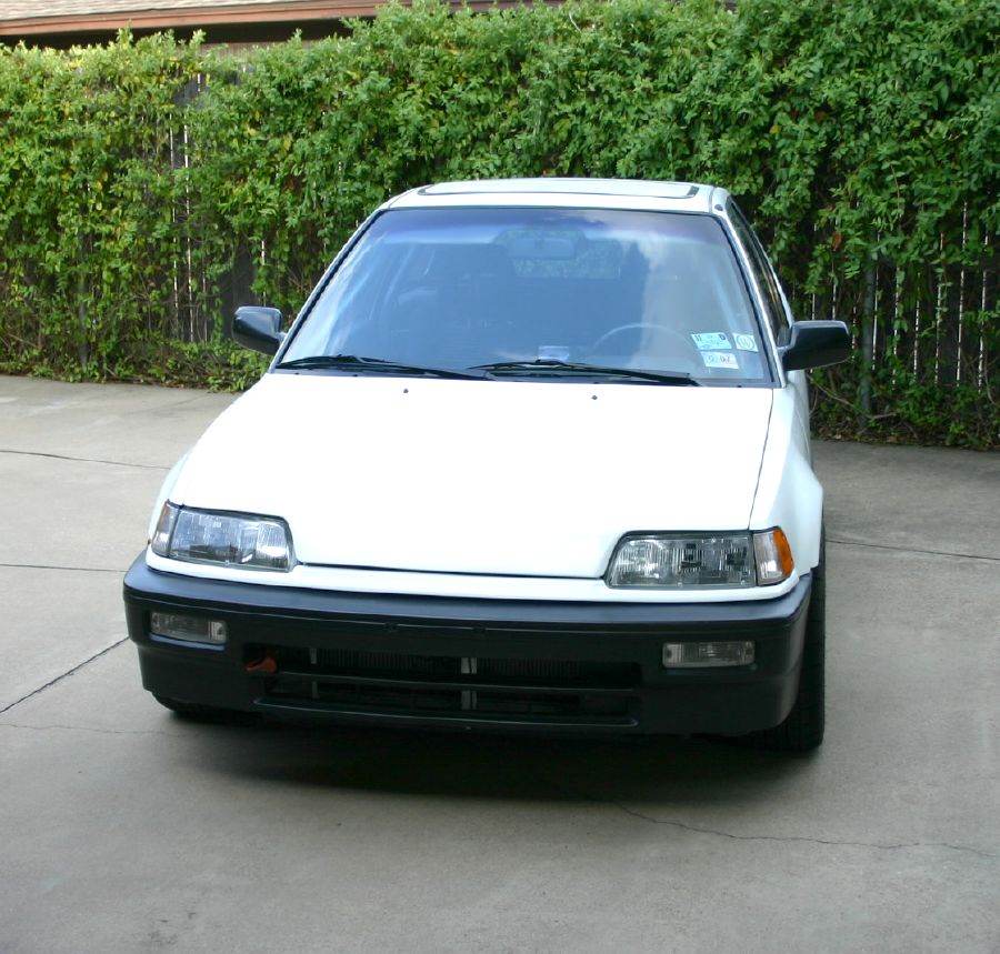
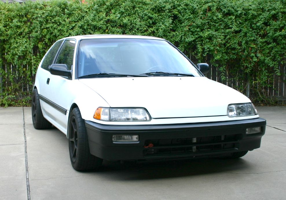
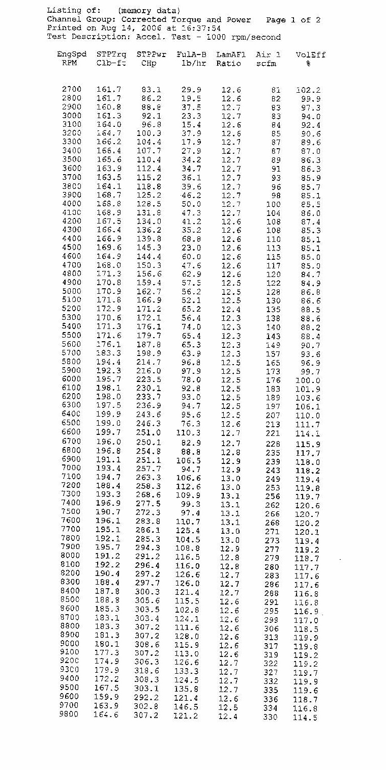
Now that the weather here has blessed us with temperatures of less than 100 degrees, I'll begin thinking about the rear fenders, but it's still going to be some time before I'm ready to do them. Next up for the car is a fabricated induction tube, some intake manifold mods, a larger throttle body, and longer secondary tubes for the header. Since building this engine, we've been hard on R&D here, and the changes I've outlined have netted some pretty sweet results on a street engine that's identical to the one in my car. An early dyno test sheet on that engine is below.....
Both of my Honda's are due for inspection in the month of November, so last Saturday I did a little tuning on the Civic. Starting with the S300 map that has "evolved" over the months of driving, we tuned the engine to run at 14.2-14.6-1 in all low rpm driving conditions. We put the idle area of the map at 16-1 and took the car in for inspection. One other change I made under the hood was removal of the filter from the front breather can and replacing it with a plug, forming an air-tight seal.
As you can see from the chart, the Texas emissions test is not as comprehensive as those in many other states, but the Civic passed with flying colors, so I'm pretty pleased. I might mention that almost a week later, and I'm still driving the car with the "emissions" tune-up in the ECU, and I may just leave it in. Were I able to spend some time on the inspection dyno, I'm sure I could better these numbers by a long shot, but at any rate, this test shows that high compression NA engines needn't be a problem when inspection time rolls around.

06-23-07
For over a year now, I've been enjoying almost every aspect of driving the car with the exception of the clutch. The green friction material has gone from being somewhat friendly to a chattering POS, that's made driving a real pain in the ass. I even had to reinforce the center of the dash to prevent it from shaking wildly on clutch release. The only way to prevent chatter has been to rev the engine to about 2500 and let the clutch out all at once, which isn't easy on the front tires, and it's next to impossible in most stop and go traffic situations. I should also mention that all the chattering broke my Quaife differential as well.
I felt that the only cure would be to replace the clutch with either a single disk unit, or go to a carbon-carbon twin. Research on the carbons that are available (CM, Comp Clutch, Tilton) has lead me to believe that they all need frequent adjustment for wear compensation and I'm looking to put a clutch in the car that is low maintenance. Subsequent conversations with a number of customers running high HP cars other than Honda's lead me to a company by the name of Carbonetics. They had just finished their first twin disk carbon clutch for the Honda B series applications and I was able to order one through my old buddy Chris Jewell at Comp Clutch. Being always cognizant of pressure plate pressure and it's effect on thrust bearings, I picked the lowest plate pressure they offered (1100kg.).
I didn't take pictures of the flywheel and clutch combination before we installed it, but it's a slick piece, using a steel flywheel with about 4lbs more weight than the aluminum unit I was running. The plates float on a single hub rather than being separate sliding pieces on the transmission input shaft, and the pressure plate cover is attached with more bolts than one can count, so buttoning it all up took some patience, but the overall installation was a piece of cake. While the transmission was out, I took the opportunity to also replace the broken Quaife with a fresh one and after all the hassle with the mechanical clutch linkage, I was dead-set on replacing that mess with a hydraulic pedal combination at the same time.
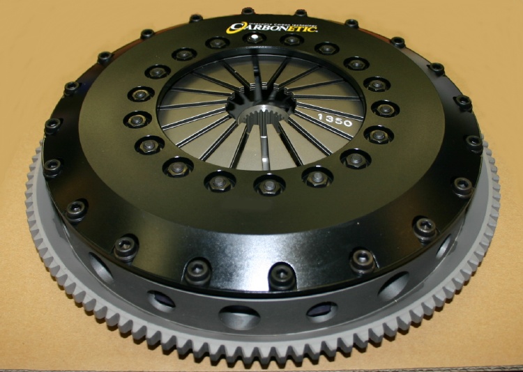
The picture above is another B series Carbonetic clutch we have at the shop. Note that this one has the heavier plate pressure (1350Kg) for use with boosted applications.
For everyone familiar with the EF Civics, you know there's no room for a second master cylinder on the firewall due to the size of the brake booster and the proximity of the read of the shock-tower, so my only option was to mount a master cylinder under the dash. Finding a reverse-mount master cylinder that would fit was the next step. After measuring a stock master cylinder bore (approximately 3/4"), I selected a unit from CNC Brakes. The assembly arrived here complete with aluminum pedal and work began to mount it.
I removed the pedal assembly from the inner firewall, cut the clutch portion off and welded a couple angle steel pieces in to locate and mount the new master cylinder.
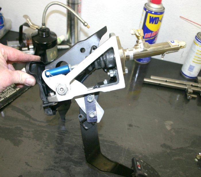
As can be seen above, the aluminum pedal / master cylinder assembly is held in place with three bolts. I cut off the pedal that came with the assembly and bolted my old clutch pedal to it. The pedal is positioned in the exact position that it was with the stock assembly in place, so I wouldn't have to get used to something new.
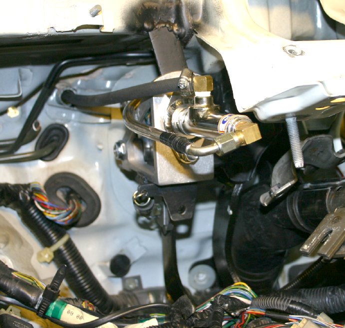
With the new assembly in the car, I decided to reinforce it with a steel tab I welded to the front base of the dash just under the windshield. It should be obvious from the picture that I had to eliminate the driver-side air duct, but that was a small sacrifice to make. Also note the tab that connects the return spring, and the tapped hole in the front of it for the upward pedal stop. The neoprene line that runs to the under-hood (Integra) fluid reservoir is visible, as is the braider steel line that runs from the master cylinder to the slave cylinder on the transmission. I acquired this piece from Stan at Fast-Turbo.com and it worked out very well. We also split some clear tubing and used it as a cover for the line to vibration wouldn't cause any chafing with wires that might be in close proximity.
After driving the combination I was really impressed. The clutch was smooth as silk and the pedal action was also very good. I run a more conventional twin disk clutch in my ITR and it only requires about 1"-1.5" total pedal travel from all the way in to to all the way out. The Civic. with it's new set up required about 2"-2.5", which was like stock. In an effort to lessen the difference between the two, I decided to order another master cylinder with a slightly larger (7/8") bore. After installation, the difference was worth it. Push the pedal about 1.5" and the clutch is fully disengaged (like the ITR's) and the action is really sweet.
Right now, I couldn't be more pleased with the combination. The clutch is smooth as can be, and it bites hard on launches and shifts. The new Quaife is making the car go straight, and I can come off turns with tires blazing in a very predictable fashion. Today I have to say that while the car is "different", and it's beginning to get back to being as much fun to drive as it was with the little blower motor.....and that's a tough combination to beat!
I still have a number of things I want to do to the engine, as we've found a lot in our testing programs, but that'll have to wait for me to make some time to do it, and right now, I don't see that on the horizon in the next month or two due to all the customer work we currently have on schedule. The upcoming changes will include a new up-dated intake manifold that'll extend the engine's effective rev range and a new header John built for me that'll offer about one more inch of ground clearance and more power to boot with a different secondary pipe configuration.
11-24-07
We finally took the time to make a skid plate for the Hytech header and lengthen the secondary tubes as well, since dyno testing had shown the longer pipes made more power across the board.
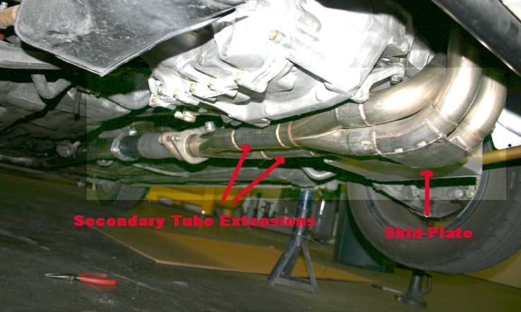
We have the new Header from John, but I have to make some changes in the system (after the collector flange) to use it. Note that we beefed-up the bottoms of the primaries, and added a skid plate. Secondary extensions are also visible. We also welded the header together as a single piece. It also has four O2 sensor bungs now, with two currently in-use.
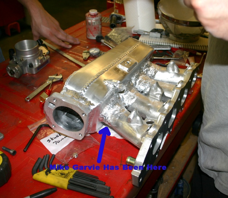
Our manifold development program has lead to some runner designs that utilize considerable taper. As you can see, master welder Mike Garvie stays busy these days adding material so we're not porting open air. Our newest fabricated manifolds use a billet throttle body flange, however, we started this one about 7-8 months ago, so it's still using the cast (cut-off) flange.
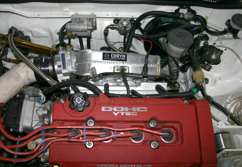
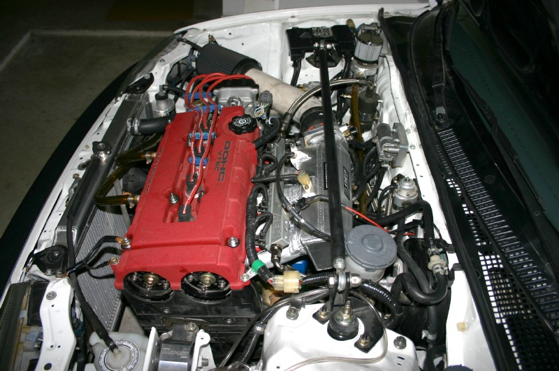
The new manifold definitely leaves more space between it's plenum and the firewall. Since I'd make the custom wire harness with the (short) wiring for the temp sensor, we welded the sensor's flange to the top of this plenum, rather than the bottom.
After a few days of driving, I replaced the Skunk2 70mm throttle body with a 68mm cast piece from Power Products. The S2 throttle body's throttle action was sticky coming off idle (regardless of how the throttle plate's position was set), making smooth street driving impossible. I fixed the problem by replacing it with a less expensive alternative....a 68mm Power Products throttle body, and drivability is sweet.
After measuring front toe-in and confirming that all was "straight", I drove the car to a local shop for a quick dyno test to see what the manifold, throttle body, and header modifications had netted. After a couple runs, I advanced the intake cam 1.5 degrees, and we were rewarded with the following pull.
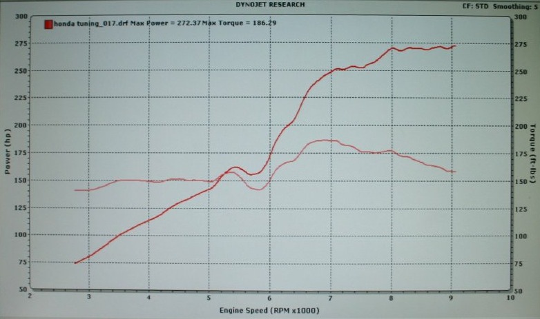
More manifold work combined with some more header pipe length changes may clean-up the (huge) VTEC cross-over dip, but I believe our latest runner taper has certainly proved torque-friendly as evidenced by the hump above 6500 rpm. This run was made running pump gas on a 104 degree August day, with heat-soaked intake air temps of 140 degrees. I believe that 280 whp is obtainable with a combination of better atmospheric conditions and a more scientifically designed induction tube/filter combination, but I can tell you this from experience.....engines that exhibit torque "bulges" like this at the bottom of the gear accelerate like there's no tomorrow....and of course, the car's even more fun to drive now.


Comment