 Tweet
Tweet
Turbo Bombas....y algunos fierros mas....
Me cope en el post de fotos de motores colgando algunos de los " motores ", mas potentes, lindos y agradables de ver, mirar y admirar....!!!
Aca , en este articulo , los SSME del Space Shuttle, en honor al transbordador espacial y el fin de su carrera, al que vuela como cohete y aterriza como avion y que desde Julio de 2011, No volara nunca mas

The Space Shuttle main engines burned liquid hydrogen and liquid oxygen from the Space Shuttle external tank. They were used for propulsion during its ascent, in addition to the two more powerful solid rocket boosters and partly the Orbital Maneuvering System. Each engine could generate almost 1.8 meganewtons (400,000 lbf) of thrust at liftoff. The engines were capable of generating a specific impulse (Isp) of 453 seconds in a vacuum, or 363 seconds at sea level (exhaust velocities of 4,440 m/s and 3,560 m/s respectively). Overall, a space shuttle main engine weighed approximately 3.2 t (7,100 lb). The engines were removed after every flight and taken to the Space Shuttle Main Engine Processing Facility (SSMEPF) for inspection and replacement of any necessary components. The cost of each SSME was approximately US$40 million.[citation needed]
The Space Shuttle's rocket engines were capable of operating at extreme temperatures. The liquid hydrogen fuel was stored at −253 °C (−423 °F). However, when burned with liquid oxygen, the temperature in the combustion chamber reached 3,300 °C (5,970 °F), higher than the boiling point of iron. Each engine consumed 1,340 L (350 US gal) of propellant per second. If the engine pumped water instead of liquid oxygen and liquid hydrogen, an average-sized swimming pool could have been drained in 75 seconds, or 25 seconds for the sum of the three used for the space shuttle launch.
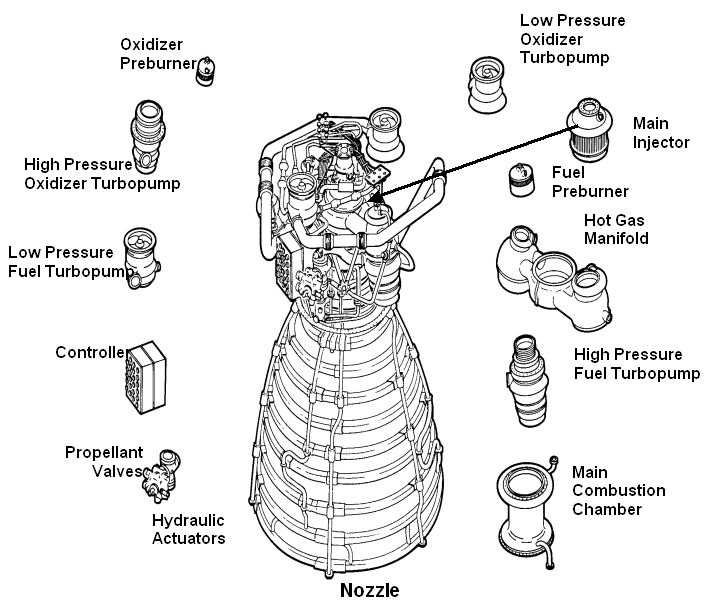
The engines perform as follows: Fuel and oxidizer from the external tank entered the orbiter at the orbiter/external tank umbilical disconnect and then the orbiter's main propulsion system feed lines. There the fuel and oxidizer each branched out into three parallel paths, one to each engine. In each branch, prevalves were opened to permit flow to the low-pressure fuel or oxidizer turbopump.
Oxidizer System
The Low Pressure Oxidizer Turbopump (LPOTP) was an axial-flow pump driven by a six-stage turbine powered by liquid oxygen. It boosted the liquid oxygen's pressure from 0.7 to 2.9 MPa (100 to 420 psi). The flow from the LPOTP was supplied to the high-pressure oxidizer turbopump (HPOTP). During engine operation, the pressure boost permitted the high-pressure oxidizer turbine to operate at high speeds without cavitating. The LPOTP operated at approximately 5,150 rpm. The LPOTP, which measured approximately 450 by 450 mm (18 by 18 in), was connected to the vehicle propellant ducting and supported in a fixed position by the orbiter structure.
The HPOTP consisted of two single-stage centrifugal pumps (a main pump and a preburner pump) mounted on a common shaft and driven by a two-stage, hot-gas turbine. The main pump boosted the liquid oxygen's pressure from 2.9 to 30 MPa (420 to 4,400 psi) while operating at approximately 28,120 rpm. The HPOTP discharge flow splits into several paths, one of which was routed to drive the LPOTP turbine. Another path was routed to and through the main oxidizer valve and entered into the main combustion chamber. Another small flow path was tapped off and sent to the oxidizer heat exchanger. The liquid oxygen flowed through an anti-flood valve that prevented it from entering the heat exchanger until sufficient heat was present to convert the liquid oxygen to gas. The heat exchanger utilized the heat contained in the discharge gases from the HPOTP turbine to convert the liquid oxygen to gas. The gas was sent to a manifold and was then routed to the external tank to pressurize the liquid oxygen tank. Another path entered the HPOT second-stage preburner pump to boost the liquid oxygen's pressure from 30 to 51 MPa (4,300 psia to 7,400 psia). It passed through the oxidizer preburner oxidizer valve into the oxidizer preburner and through the fuel preburner oxidizer valve into the fuel preburner. The HPOTP measured approximately 600 by 900 mm (24 by 35 in). It was attached by flanges to the hot-gas manifold.
The HPOTP turbine and HPOTP pumps were mounted on a common shaft. Mixing of the fuel-rich hot gas in the turbine section and the liquid oxygen in the main pump could create a hazard. To prevent this, the two sections were separated by a cavity that was continuously purged by the MPS engine helium supply during engine operation. Two seals minimized leakage into the cavity. One seal was located between the turbine section and the cavity, and the other was between the pump section and cavity. Loss of helium pressure in this cavity resulted in an automatic engine shutdown.

Hydrogen fuel system
Fuel entered the orbiter at the liquid hydrogen feed line disconnect valve, then flowed into the orbiter liquid hydrogen feed line manifold and branches out into three parallel paths to each engine. In each liquid hydrogen branch, a prevalve permitted liquid hydrogen to flow to the low-pressure fuel turbopump when the prevalve was open.
The low-pressure fuel turbopump (LPFTP) was an axial-flow pump driven by a two-stage turbine powered by gaseous hydrogen. It boosted the pressure of the liquid hydrogen from 30 to 276 psia (0.2 to 1.9 MPa) and supplies it to the high-pressure fuel turbopump (HPFTP). During engine operation, the pressure boost provided by the LPFTP permitted the HPFTP to operate at high speeds without cavitating. The LPFTP operated at approximately 16,185 rpm. The LPFTP was approximately 450 by 600 mm (18 by 24 in). It was connected to the vehicle propellant ducting and was supported in a fixed position by the orbiter structure 180 degrees from the LPOTP.
The HPFTP was a three-stage centrifugal pump driven by a two-stage, hot-gas turbine. It boosted the pressure of the liquid hydrogen from 1.9 to 45 MPa (276 to 6,515 psia). The HPFTP operated at approximately 35,360 rpm. The discharge flow from the turbopump was routed to and through the main valve and then split into three flow paths. One path was through the jacket of the main combustion chamber, where the hydrogen ws used to cool the chamber walls. It was then routed from the main combustion chamber to the LPFTP, where it was used to drive the LPFTP turbine. A small portion of the flow from the LPFTP was then directed to a common manifold from all three engines to form a single path to the external tank to maintain liquid hydrogen tank pressurization. The remaining hydrogen passes between the inner and outer walls to cool the hot-gas manifold and was discharged into the main combustion chamber. The second hydrogen flow path from the main fuel valve was through the engine nozzle (to cool the nozzle). It then joined the third flow path from the chamber coolant valve. The combined flow was then directed to the fuel and oxidizer preburners. The HPFTP was approximately 550 by 1,100 mm (22 by 43 in). It was attached by flanges to the hot-gas manifold.
The oxidizer and fuel preburners were welded to the hot-gas manifold. The fuel and oxidizer entered the preburners and were mixed so that efficient combustion can occur. The augmented spark igniter was a small combination chamber located in the center of the injector of each preburner. The two dual-redundant spark igniters, which were activated by the engine controller, were used during the engine start sequence to initiate combustion in each preburner. They were turned off after approximately three seconds because the combustion process was then self-sustaining. The preburners produce the fuel-rich hot gas that passed through the turbines to generate the power to operate the high-pressure turbopumps. The oxidizer preburner's outflow drives a turbine that was connected to the HPOTP and the oxidizer preburner pump. The fuel preburner's outflow drives a turbine that was connected to the HPFTP.
The speed of the HPOTP and HPFTP turbines depended on the position of the corresponding oxidizer and fuel preburner oxidizer valves. These valves were positioned by the engine controller, which used them to throttle the flow of liquid oxygen to the preburners and, thus, control engine thrust. The oxidizer and fuel preburner oxidizer valves increased or decreased the liquid oxygen flow, thus increasing or decreasing preburner chamber pressure, HPOTP and HPFTP turbine speed, and liquid oxygen and gaseous hydrogen flow into the main combustion chamber, which increased or decreased engine thrust, thus throttling the engine. The oxidizer and fuel preburner valves operated together to throttle the engine and maintain a constant 6-1 propellant mixture ratio.
The main oxidizer valve and the main fuel valve control the flow of liquid oxygen and liquid hydrogen into the engine and were controlled by each engine controller. When an engine was operating, the main valves were fully open.
Combustion chamber and nozzle

Each engine main combustion chamber received fuel-rich hot gas from a hot-gas manifold cooling circuit. The gaseous hydrogen and liquid oxygen enter the chamber at the injector, which mixed the propellants. A small augmented spark igniter chamber was located in the center of the injector. The dual-redundant igniter was used during the engine start sequence to initiate combustion. The igniters were turned off after approximately three seconds because the combustion process was self-sustaining. The main injector and dome assembly was welded to the hot-gas manifold. The main combustion chamber also was bolted to the hot-gas manifold.
The inner surface of each combustion chamber, as well as the inner surface of each nozzle, was cooled by liquid hydrogen flowing through brazed stainless steel tube-wall coolant passages. The nozzle assembly was a bell-shaped extension bolted to the main combustion chamber. The nozzle was 2.9 m (110 in) long, and the outside diameter of the exit was 2.4 m (94 in). A support ring welded to the forward end of the nozzle was the engine attach point to the orbiter-supplied heat shield. Thermal protection was necessary because of the exposure portions of the nozzles experience during the launch, ascent, on-orbit and entry phases of a mission. The insulation consists of four layers of metallic batting covered with a metallic foil and screening.
For a nozzle able to run at sea level, the SSME nozzle had an unusually large expansion ratio (about 77) for the chamber pressure. A nozzle that large would normally undergo flow separation of the jet from the nozzle which would cause control difficulties and could even mechanically damage the vehicle. Instead the Rocketdyne engineers varied the angle of the nozzle, reducing it near the exit. This raised the pressure just around the rim to between 4.6 and 5.7 psi (32 and 39 kPa), and prevents flow separation. The inner part of the flow was at much lower pressure, around 2 psi (14 kPa) or less
" La ECU "
Controller
An important innovation was the inclusion of an integrated controller in the engine itself: the SSME controller. This digital computer (originally composed of two redundant Honeywell HDC-601 computers,[5] and later replaced with a system with two double-redundant Motorola 68000 processors[6] for a total of 4 M68000s per controller) had two tasks: control the engine's burning process, and check itself. This arrangement greatly simplified the wiring between the engine and the shuttle, because all the sensors and actuators were connected directly to only the controller. Using a dedicated system also simplified the software and improved its reliability.
Two independent, dual-CPU computers, A and B, form the controller, giving redundancy to the system. The failure of controller system A will automatically switch to controller system B without impeding operational capabilities; the subsequent failure of controller system B will provide a graceful shutdown of the engine.
Within each system (A and B), the two M68000s operate in "lock-step", thereby enabling each system to detect failures by comparing the TTL signal levels of the buses of the two M68000 processors within that system. If differences were encountered between the two buses, then an interrupt was generated and control turned over to the other system. Because of subtle differences M68000s from Motorola and the second source manufacturer TRW, each system uses M68000s from the same manufacturer. (i.e. System A would have two Motorola CPUs while System B would have two CPUs manufactured by TRW.)
Memory for both Block I and Block II Main Engine Controllers were of the "plated-wire" type. Plated-wire memory functions in a manner similar to magnetic core memory and retains data even after power was turned off. (In the investigation of the Challenger accident, the MECs that were recovered from the seafloor were delivered to Honeywell for examination and analysis. Despite having been immersed in salt water for some time, after cleanup and some minor repairs, it was determined that the memory data was intact and Honeywell technicians were able to extract the memory contents for forensic examination.)
En los rolos midio .....
Thrust specifications
SSME thrust (or power level) can be throttled between 67 to 109% of rated thrust. Current launches use 104.5%, with 106 or 109% available for abort contingencies. Thrust can be specified as sea level or vacuum thrust. Vacuum thrust will be higher due to the absence of atmospheric effects.
Sea levelVacuum100% thrust1,670 kN (380,000 lbf)2,090 kN (470,000 lbf)104.5% thrust1,750 kN (390,000 lbf)2,170 kN (490,000 lbf)109% thrust1,860 kN (420,000 lbf)2,280 kN (510,000 lbf)
Specifying power levels over 100% may seem nonsensical, but there was a logic behind it. The 100% level does not mean the maximum physical power level attainable. Rather it was a specification, decided on early during SSME development, for the expected rated power level. Later studies indicated the engine could operate safely at levels above 100%, which was now the norm. Maintaining the original relationship of power level to physical thrust helps reduce confusion. It created an unvarying fixed relationship, so that test data, or operational data from past or future missions can be easily compared. If each time the power level was increased, that value was made 100%, then all previous data and documentation would either require changing, or cross-checking against what physical thrust corresponded to 100% power level on that date.
SSME power level affects engine reliability. Studies indicate the probability of an engine failure increased rapidly with power levels over 104.5%, which was why those were retained for contingency use only


Las Specs, para los que solo sueñan con los numeros....
Nozzle
The SSME nozzle diameter was 10.3 in (0.26 m) at the throat and 90.7 in (2.30 m) at the nozzle exit, with a length of 121 in (3.1 m).[15]
[edit] General
Specifications as listed in the Encyclopedia Astronautix[citation needed]

En el taller, despues de cada vuelo

Las fuentes.:
http://www.shuttlepresskit.com/scom/216.pdf}
Y donde esta todo, ( por cierto, es bastante tecnico el articulo, NO ??? )
Space Shuttle main engine - Wikipedia, the free encyclopedia
Me cope en el post de fotos de motores colgando algunos de los " motores ", mas potentes, lindos y agradables de ver, mirar y admirar....!!!
Aca , en este articulo , los SSME del Space Shuttle, en honor al transbordador espacial y el fin de su carrera, al que vuela como cohete y aterriza como avion y que desde Julio de 2011, No volara nunca mas
The Space Shuttle main engines burned liquid hydrogen and liquid oxygen from the Space Shuttle external tank. They were used for propulsion during its ascent, in addition to the two more powerful solid rocket boosters and partly the Orbital Maneuvering System. Each engine could generate almost 1.8 meganewtons (400,000 lbf) of thrust at liftoff. The engines were capable of generating a specific impulse (Isp) of 453 seconds in a vacuum, or 363 seconds at sea level (exhaust velocities of 4,440 m/s and 3,560 m/s respectively). Overall, a space shuttle main engine weighed approximately 3.2 t (7,100 lb). The engines were removed after every flight and taken to the Space Shuttle Main Engine Processing Facility (SSMEPF) for inspection and replacement of any necessary components. The cost of each SSME was approximately US$40 million.[citation needed]
The Space Shuttle's rocket engines were capable of operating at extreme temperatures. The liquid hydrogen fuel was stored at −253 °C (−423 °F). However, when burned with liquid oxygen, the temperature in the combustion chamber reached 3,300 °C (5,970 °F), higher than the boiling point of iron. Each engine consumed 1,340 L (350 US gal) of propellant per second. If the engine pumped water instead of liquid oxygen and liquid hydrogen, an average-sized swimming pool could have been drained in 75 seconds, or 25 seconds for the sum of the three used for the space shuttle launch.
The engines perform as follows: Fuel and oxidizer from the external tank entered the orbiter at the orbiter/external tank umbilical disconnect and then the orbiter's main propulsion system feed lines. There the fuel and oxidizer each branched out into three parallel paths, one to each engine. In each branch, prevalves were opened to permit flow to the low-pressure fuel or oxidizer turbopump.
Oxidizer System
The Low Pressure Oxidizer Turbopump (LPOTP) was an axial-flow pump driven by a six-stage turbine powered by liquid oxygen. It boosted the liquid oxygen's pressure from 0.7 to 2.9 MPa (100 to 420 psi). The flow from the LPOTP was supplied to the high-pressure oxidizer turbopump (HPOTP). During engine operation, the pressure boost permitted the high-pressure oxidizer turbine to operate at high speeds without cavitating. The LPOTP operated at approximately 5,150 rpm. The LPOTP, which measured approximately 450 by 450 mm (18 by 18 in), was connected to the vehicle propellant ducting and supported in a fixed position by the orbiter structure.
The HPOTP consisted of two single-stage centrifugal pumps (a main pump and a preburner pump) mounted on a common shaft and driven by a two-stage, hot-gas turbine. The main pump boosted the liquid oxygen's pressure from 2.9 to 30 MPa (420 to 4,400 psi) while operating at approximately 28,120 rpm. The HPOTP discharge flow splits into several paths, one of which was routed to drive the LPOTP turbine. Another path was routed to and through the main oxidizer valve and entered into the main combustion chamber. Another small flow path was tapped off and sent to the oxidizer heat exchanger. The liquid oxygen flowed through an anti-flood valve that prevented it from entering the heat exchanger until sufficient heat was present to convert the liquid oxygen to gas. The heat exchanger utilized the heat contained in the discharge gases from the HPOTP turbine to convert the liquid oxygen to gas. The gas was sent to a manifold and was then routed to the external tank to pressurize the liquid oxygen tank. Another path entered the HPOT second-stage preburner pump to boost the liquid oxygen's pressure from 30 to 51 MPa (4,300 psia to 7,400 psia). It passed through the oxidizer preburner oxidizer valve into the oxidizer preburner and through the fuel preburner oxidizer valve into the fuel preburner. The HPOTP measured approximately 600 by 900 mm (24 by 35 in). It was attached by flanges to the hot-gas manifold.
The HPOTP turbine and HPOTP pumps were mounted on a common shaft. Mixing of the fuel-rich hot gas in the turbine section and the liquid oxygen in the main pump could create a hazard. To prevent this, the two sections were separated by a cavity that was continuously purged by the MPS engine helium supply during engine operation. Two seals minimized leakage into the cavity. One seal was located between the turbine section and the cavity, and the other was between the pump section and cavity. Loss of helium pressure in this cavity resulted in an automatic engine shutdown.
Hydrogen fuel system
Fuel entered the orbiter at the liquid hydrogen feed line disconnect valve, then flowed into the orbiter liquid hydrogen feed line manifold and branches out into three parallel paths to each engine. In each liquid hydrogen branch, a prevalve permitted liquid hydrogen to flow to the low-pressure fuel turbopump when the prevalve was open.
The low-pressure fuel turbopump (LPFTP) was an axial-flow pump driven by a two-stage turbine powered by gaseous hydrogen. It boosted the pressure of the liquid hydrogen from 30 to 276 psia (0.2 to 1.9 MPa) and supplies it to the high-pressure fuel turbopump (HPFTP). During engine operation, the pressure boost provided by the LPFTP permitted the HPFTP to operate at high speeds without cavitating. The LPFTP operated at approximately 16,185 rpm. The LPFTP was approximately 450 by 600 mm (18 by 24 in). It was connected to the vehicle propellant ducting and was supported in a fixed position by the orbiter structure 180 degrees from the LPOTP.
The HPFTP was a three-stage centrifugal pump driven by a two-stage, hot-gas turbine. It boosted the pressure of the liquid hydrogen from 1.9 to 45 MPa (276 to 6,515 psia). The HPFTP operated at approximately 35,360 rpm. The discharge flow from the turbopump was routed to and through the main valve and then split into three flow paths. One path was through the jacket of the main combustion chamber, where the hydrogen ws used to cool the chamber walls. It was then routed from the main combustion chamber to the LPFTP, where it was used to drive the LPFTP turbine. A small portion of the flow from the LPFTP was then directed to a common manifold from all three engines to form a single path to the external tank to maintain liquid hydrogen tank pressurization. The remaining hydrogen passes between the inner and outer walls to cool the hot-gas manifold and was discharged into the main combustion chamber. The second hydrogen flow path from the main fuel valve was through the engine nozzle (to cool the nozzle). It then joined the third flow path from the chamber coolant valve. The combined flow was then directed to the fuel and oxidizer preburners. The HPFTP was approximately 550 by 1,100 mm (22 by 43 in). It was attached by flanges to the hot-gas manifold.
The oxidizer and fuel preburners were welded to the hot-gas manifold. The fuel and oxidizer entered the preburners and were mixed so that efficient combustion can occur. The augmented spark igniter was a small combination chamber located in the center of the injector of each preburner. The two dual-redundant spark igniters, which were activated by the engine controller, were used during the engine start sequence to initiate combustion in each preburner. They were turned off after approximately three seconds because the combustion process was then self-sustaining. The preburners produce the fuel-rich hot gas that passed through the turbines to generate the power to operate the high-pressure turbopumps. The oxidizer preburner's outflow drives a turbine that was connected to the HPOTP and the oxidizer preburner pump. The fuel preburner's outflow drives a turbine that was connected to the HPFTP.
The speed of the HPOTP and HPFTP turbines depended on the position of the corresponding oxidizer and fuel preburner oxidizer valves. These valves were positioned by the engine controller, which used them to throttle the flow of liquid oxygen to the preburners and, thus, control engine thrust. The oxidizer and fuel preburner oxidizer valves increased or decreased the liquid oxygen flow, thus increasing or decreasing preburner chamber pressure, HPOTP and HPFTP turbine speed, and liquid oxygen and gaseous hydrogen flow into the main combustion chamber, which increased or decreased engine thrust, thus throttling the engine. The oxidizer and fuel preburner valves operated together to throttle the engine and maintain a constant 6-1 propellant mixture ratio.
The main oxidizer valve and the main fuel valve control the flow of liquid oxygen and liquid hydrogen into the engine and were controlled by each engine controller. When an engine was operating, the main valves were fully open.
Combustion chamber and nozzle
Each engine main combustion chamber received fuel-rich hot gas from a hot-gas manifold cooling circuit. The gaseous hydrogen and liquid oxygen enter the chamber at the injector, which mixed the propellants. A small augmented spark igniter chamber was located in the center of the injector. The dual-redundant igniter was used during the engine start sequence to initiate combustion. The igniters were turned off after approximately three seconds because the combustion process was self-sustaining. The main injector and dome assembly was welded to the hot-gas manifold. The main combustion chamber also was bolted to the hot-gas manifold.
The inner surface of each combustion chamber, as well as the inner surface of each nozzle, was cooled by liquid hydrogen flowing through brazed stainless steel tube-wall coolant passages. The nozzle assembly was a bell-shaped extension bolted to the main combustion chamber. The nozzle was 2.9 m (110 in) long, and the outside diameter of the exit was 2.4 m (94 in). A support ring welded to the forward end of the nozzle was the engine attach point to the orbiter-supplied heat shield. Thermal protection was necessary because of the exposure portions of the nozzles experience during the launch, ascent, on-orbit and entry phases of a mission. The insulation consists of four layers of metallic batting covered with a metallic foil and screening.
For a nozzle able to run at sea level, the SSME nozzle had an unusually large expansion ratio (about 77) for the chamber pressure. A nozzle that large would normally undergo flow separation of the jet from the nozzle which would cause control difficulties and could even mechanically damage the vehicle. Instead the Rocketdyne engineers varied the angle of the nozzle, reducing it near the exit. This raised the pressure just around the rim to between 4.6 and 5.7 psi (32 and 39 kPa), and prevents flow separation. The inner part of the flow was at much lower pressure, around 2 psi (14 kPa) or less
" La ECU "
Controller
An important innovation was the inclusion of an integrated controller in the engine itself: the SSME controller. This digital computer (originally composed of two redundant Honeywell HDC-601 computers,[5] and later replaced with a system with two double-redundant Motorola 68000 processors[6] for a total of 4 M68000s per controller) had two tasks: control the engine's burning process, and check itself. This arrangement greatly simplified the wiring between the engine and the shuttle, because all the sensors and actuators were connected directly to only the controller. Using a dedicated system also simplified the software and improved its reliability.
Two independent, dual-CPU computers, A and B, form the controller, giving redundancy to the system. The failure of controller system A will automatically switch to controller system B without impeding operational capabilities; the subsequent failure of controller system B will provide a graceful shutdown of the engine.
Within each system (A and B), the two M68000s operate in "lock-step", thereby enabling each system to detect failures by comparing the TTL signal levels of the buses of the two M68000 processors within that system. If differences were encountered between the two buses, then an interrupt was generated and control turned over to the other system. Because of subtle differences M68000s from Motorola and the second source manufacturer TRW, each system uses M68000s from the same manufacturer. (i.e. System A would have two Motorola CPUs while System B would have two CPUs manufactured by TRW.)
Memory for both Block I and Block II Main Engine Controllers were of the "plated-wire" type. Plated-wire memory functions in a manner similar to magnetic core memory and retains data even after power was turned off. (In the investigation of the Challenger accident, the MECs that were recovered from the seafloor were delivered to Honeywell for examination and analysis. Despite having been immersed in salt water for some time, after cleanup and some minor repairs, it was determined that the memory data was intact and Honeywell technicians were able to extract the memory contents for forensic examination.)
En los rolos midio .....
Thrust specifications
SSME thrust (or power level) can be throttled between 67 to 109% of rated thrust. Current launches use 104.5%, with 106 or 109% available for abort contingencies. Thrust can be specified as sea level or vacuum thrust. Vacuum thrust will be higher due to the absence of atmospheric effects.
Sea levelVacuum100% thrust1,670 kN (380,000 lbf)2,090 kN (470,000 lbf)104.5% thrust1,750 kN (390,000 lbf)2,170 kN (490,000 lbf)109% thrust1,860 kN (420,000 lbf)2,280 kN (510,000 lbf)
Specifying power levels over 100% may seem nonsensical, but there was a logic behind it. The 100% level does not mean the maximum physical power level attainable. Rather it was a specification, decided on early during SSME development, for the expected rated power level. Later studies indicated the engine could operate safely at levels above 100%, which was now the norm. Maintaining the original relationship of power level to physical thrust helps reduce confusion. It created an unvarying fixed relationship, so that test data, or operational data from past or future missions can be easily compared. If each time the power level was increased, that value was made 100%, then all previous data and documentation would either require changing, or cross-checking against what physical thrust corresponded to 100% power level on that date.
SSME power level affects engine reliability. Studies indicate the probability of an engine failure increased rapidly with power levels over 104.5%, which was why those were retained for contingency use only
Las Specs, para los que solo sueñan con los numeros....
Nozzle
The SSME nozzle diameter was 10.3 in (0.26 m) at the throat and 90.7 in (2.30 m) at the nozzle exit, with a length of 121 in (3.1 m).[15]
[edit] General
Specifications as listed in the Encyclopedia Astronautix[citation needed]
- Engine Model: SSME
- Manufacturer Name: RS-25
- Other Designations: RS-24
- Designer: Rocketdyne
- Developed in: 1972
- Propellants: Lox/LH2
- Thrust(vac): 2,278,000 newtons (512,000 lbf)
- Thrust(sl): 1,817,400 newtons (408,600 lbf)
- Isp: 453 s
- Isp (sea level): 363 s
- Burn time: 480 s
- Mass Engine: 3,177 kilograms (7,000 lb)
- Diameter: 1.63 metres (5.3 ft)
- Length: 4.24 metres (13.9 ft)
- Chambers: 1
- Chamber Pressure: 204.08 bars (2,959.9 psi)
- Area Ratio: 77.50
- Oxidizer to Fuel Ratio: 6.00
- Thrust to Weight Ratio: 73.12
- Country: USA.
- Status: In production
- First Flight: 1981
- Design altitude: 60,000 feet (18,300 m)
- Nozzle Mach number: 6.55 (ideally expanded) (4.7 calculated via expansion ratio and frozen gamma of 1.20)
- Throat area: 93 square inches (600 cm2)
- Nozzle area: 50.265 square feet (4.6698 m2)
- Chamber pressure: 2,747 pounds per square inch (18,940 kPa) at 100% power
- Exit pressure: 1.049 pounds per square inch (7.23 kPa) (calculated) (calculated value based on 490850 lbf of thrust and roughly 7,200 square inches (4.6 m2) of nozzle area, dynamic exit pressure was more like 68 pounds per square inch (470 kPa) absolute)
- Burn time: 520 s
- Vacuum Isp: 452.5 s
- Vacuum thrust per engine: 490,850 pounds-force (0 MN) at 104.5% of design thrust
En el taller, despues de cada vuelo
Las fuentes.:
http://www.shuttlepresskit.com/scom/216.pdf}
Y donde esta todo, ( por cierto, es bastante tecnico el articulo, NO ??? )
Space Shuttle main engine - Wikipedia, the free encyclopedia


 el sonido es HERMOSO!!!
Comment